
Electrophoretic paint uniform-speed stirring device based on resistance adjustment

A stirring device and resistance adjustment technology, which is applied to mixers with rotating stirring devices, mixer accessories, transportation and packaging, etc., can solve the problems of self-regulation of motor speed, reduce the effect of stirring, reduce efficiency, etc., and achieve the reduction of resistance , Improve efficiency, improve the effect of stirring range

Active Publication Date: 2020-09-18
山东振通机械科技有限公司
View PDF11 Cites 12 Cited by
  • Summary
  • Abstract
  • Description
  • Claims
  • Application Information

AI Technical Summary

Problems solved by technology

[0003] The stirring blades inside the traditional stirring device are fixed indefinitely. In order to have a wider stirring area, they are distributed in a large horizontal area inside the stirring tank. However, due to the high concentration of electrophoretic paint, after the stirring is completed, the traditional large-area stirring blades It will hinder the normal outflow of the electrophoretic paint after stirring, thereby reducing the working efficiency, and in the process of stirring the electrophoretic paint and the compound agent, it is necessary to keep stirring at a constant speed, and the traditional device cannot self-adjust the speed of the motor, so that the motor The speed will change under the influence of external factors, which will reduce the effect of stirring

Method used


Image

  • Electrophoretic paint uniform-speed stirring device based on resistance adjustment
  • Electrophoretic paint uniform-speed stirring device based on resistance adjustment
  • Electrophoretic paint uniform-speed stirring device based on resistance adjustment

Examples


Embodiment Construction

[0022] The following will clearly and completely describe the technical solutions in the embodiments of the present invention with reference to the accompanying drawings in the embodiments of the present invention. Obviously, the described embodiments are only some, not all, embodiments of the present invention. Based on the embodiments of the present invention, all other embodiments obtained by persons of ordinary skill in the art without making creative efforts belong to the protection scope of the present invention.

[0023] The embodiment of this electrophoretic paint uniform stirring device based on resistance adjustment is as follows:

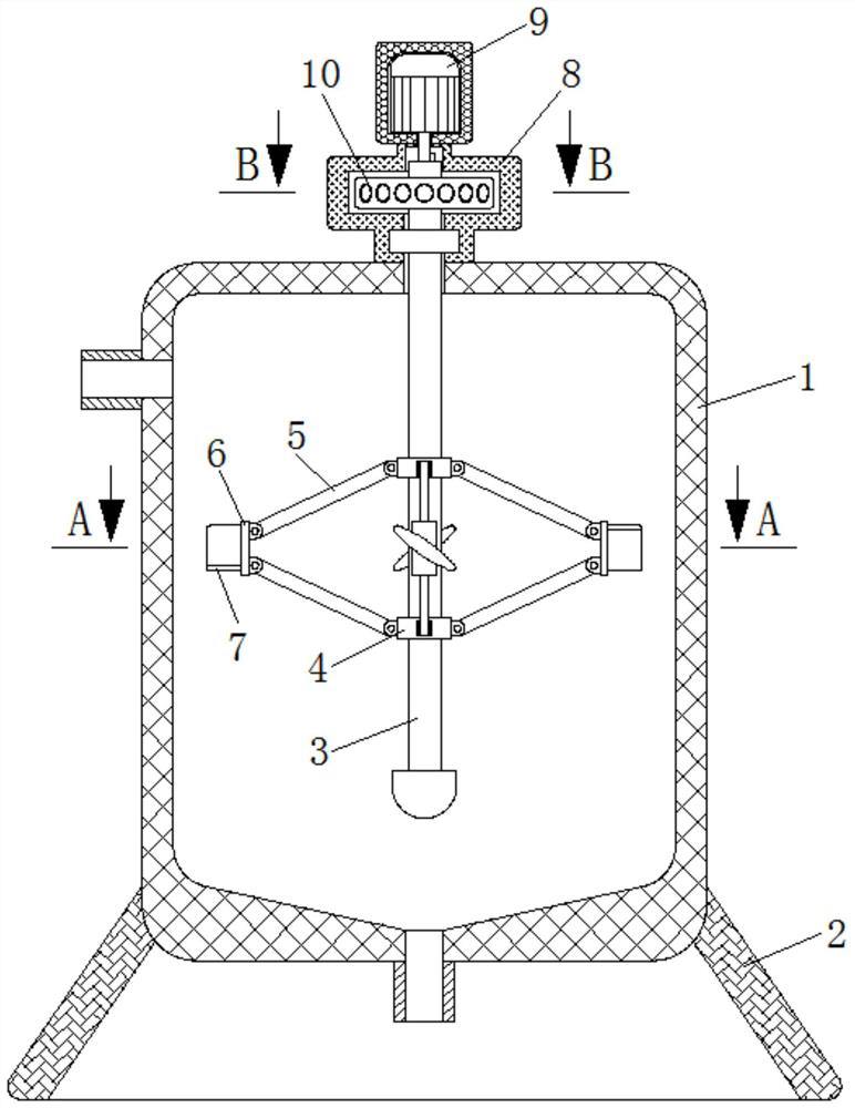
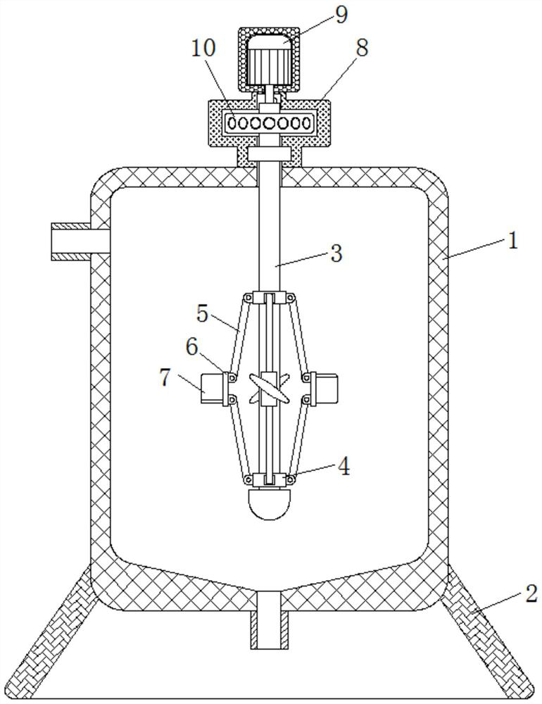
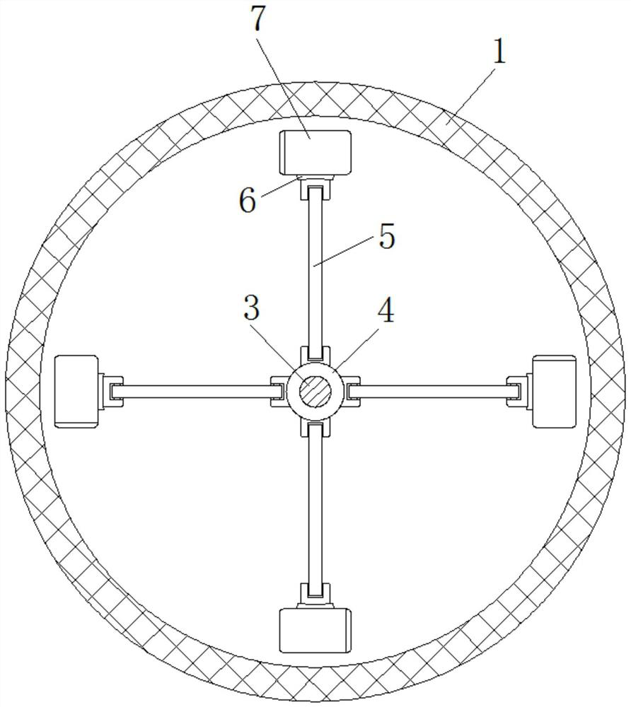
[0024] see Figure 1-5 , a constant-speed electrophoretic paint stirring device based on resistance adjustment, including a housing 1, a base 2, a rotating shaft 3, a collar 4, a transmission rod 5, a connecting plate 6, a stirring blade 7, a sleeve 8, a motor 9, a turntable 10, Elastic block 11, slide plate 12, spring 13, resistance wir...


PUM


Abstract

The invention provides an electrophoretic paint uniform-speed stirring device based on resistance adjustment, and relates to the technical field of electrophoretic paint stirring. The electrophoreticpaint uniform-speed stirring device based on resistance adjustment includes a housing; a base is fixedly mounted at the bottom end of the shell; a rotating shaft is rotatably connected to the interiorof the shell; a lantern ring is slidably connected to the periphery of the rotating shaft, a transmission rod is in transmission connection between the lantern ring and the periphery of the top of the rotating shaft, a connecting plate is rotatably connected to the periphery of the transmission rod, stirring blades are fixedly mounted at the end, away from the transmission rod, of the connectingplate, and a sleeve is fixedly mounted at the top end of the shell. According to the electrophoretic paint uniform-speed stirring device based on resistance adjustment, the stirring range can be guaranteed, meanwhile, after stirring is completed, flowing-out of an electrophoretic paint can be facilitated, then the working efficiency is improved, self-adjustment of the rotating speed of the motor is achieved, the motor can better drive the rotating shaft to rotate at a uniform speed, and the stirring effect is improved.

Description

technical field [0001] The invention relates to the technical field of electrophoretic paint stirring, in particular to a constant-speed stirring device for electrophoretic paint based on resistance adjustment. Background technique [0002] Electrophoretic paint, also called electrophoretic paint, as the defects of conventional spraying continue to emerge, electrophoretic paint has become more and more popular, and electrophoretic paint has also begun to be continuously updated. The development of electrophoretic paint has also promoted the development of electrophoretic paint, making more and more Our products no longer use spraying technology but electrophoresis. When electrophoresis is performed, before adding the electrophoretic paint to the electric pool, the electrophoretic paint and the compound agent need to be fully stirred to improve the electrophoretic effect. [0003] The stirring blades inside the traditional stirring device are fixed indefinitely. In order to h...

Claims


Application Information

Patent Timeline
Patent Type & Authority Applications(China)
IPC IPC(8): B01F7/32B01F7/00B01F15/00B01F27/96
CPCB01F27/0542B01F27/96B01F35/30B01F35/331B01F2101/30
Inventor 董银屏方茂霖
Owner 山东振通机械科技有限公司
Learn More