
Mechanical automatic spraying device based on computer vision

An automatic spraying and computer vision technology, which is applied in the direction of spraying devices, spray booths, chemical instruments and methods, etc., can solve the problems of too thick local paint, not easy to solidify and form, and uneven spraying, so as to achieve uniform spraying intensity, reduce waste, The effect of spraying paint evenly

Active Publication Date: 2020-12-18
TARIM UNIV
View PDF23 Cites 4 Cited by
  • Summary
  • Abstract
  • Description
  • Claims
  • Application Information

AI Technical Summary

Problems solved by technology

[0002] Round pipes are widely used in our production and life. Commonly used are water pipes, gas pipes, wire pipes, etc., and one of the necessary links for most round pipes is painting. The main function of round pipe painting is protection and extended use. Longevity prevents the pipes from rusting. Part of the round pipes can be painted for heat insulation and fire prevention. Of course, it also has an aesthetic purpose. At the same time, try to ensure that the paint is evenly sprayed to prevent the paint skin on the outside of the round tube from easily cracking and falling off, so that it will no longer protect the round tube. Since the cross section of the round tube is circular, the outer arc of the round tube When spraying paint on the surface, it is easy to spray paint unevenly, and the local paint is too thick, which is not easy to solidify and form. At the same time, due to the curved surface outside the round tube, a large amount of paint mist will not be sprayed on the surface of the round tube, resulting in waste.

Method used


Image

  • Mechanical automatic spraying device based on computer vision
  • Mechanical automatic spraying device based on computer vision
  • Mechanical automatic spraying device based on computer vision

Examples


Embodiment Construction

[0017]In order to make the objectives, technical solutions, and advantages of the embodiments of the present invention clearer, the technical solutions in the embodiments of the present invention will be described clearly and completely in conjunction with the accompanying drawings in the embodiments of the present invention. Obviously, the described embodiments It is a part of the embodiments of the present invention, not all the embodiments. Based on the embodiments of the present invention, all other embodiments obtained by those of ordinary skill in the art without creative work shall fall within the protection scope of the present invention.

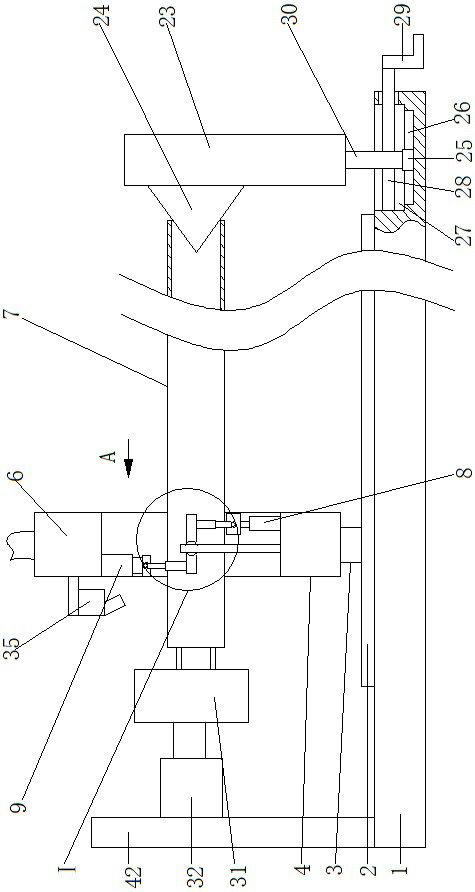
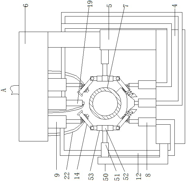
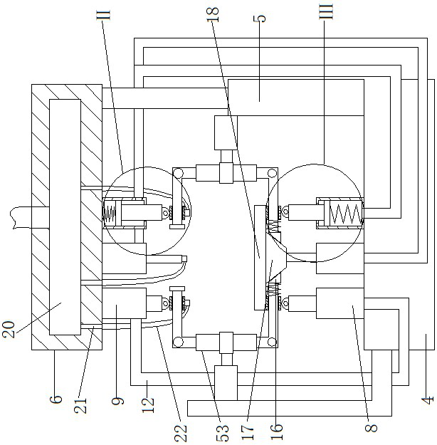
[0018] A mechanical automatic spraying device based on computer vision, as shown in the figure, includes a base 1, above the base 1 is provided with a circular tube clamping device 31, the circular tube clamping device 31 clamps a horizontal circular tube 7, the circular tube The clamping device 31 is driven by the driving device. The right...


PUM


Abstract

A mechanical automatic spraying device based on computer vision comprises a base. A round pipe clamping device is arranged above the base, a transverse round pipe is clamped by the round pipe clampingdevice, an auxiliary positioning device corresponding to the round pipe is arranged on the right side of the base, and a transverse electric sliding rail is fixedly installed at the top of the base.An electric sliding block is installed at the top of the electric sliding rail in a matched mode, a bottom plate is fixedly installed at the top of the electric sliding block, and three first cylinderbodies arranged at equal intervals in the front-back direction are fixedly installed at the top of the bottom plate. According to the device, by clamping round pipes of different diameters, three piston rods on the lower side are pressed downwards to move by different distances, paint is more uniformly sprayed on the outer surfaces of the round pipes, colors are more consistent, and meanwhile, spraying openings of three spraying heads on the upper side are all perpendicular to the outer surfaces of the round pipes. Therefore, painting mist may be completely sprayed to the outer side faces ofthe round pipes more easily during paint spraying, waste of paint is reduced, and the uniformity of paint spraying is further enhanced.

Description

Technical field[0001]The invention belongs to the field of spraying devices, in particular to a mechanical automatic spraying device based on computer vision.Background technique[0002]Round pipes are widely used in our production and life. Commonly used are water pipes, gas pipes, wire pipes, etc., and one of the necessary links of most round pipes is painting. The main function of round pipe painting is protection and prolonged use. The service life prevents the pipeline from rusting. Part of the round pipe painting can also have the effect of heat insulation and fire prevention. Of course, it also has beautiful uses. In order to ensure the long-term use of the paint after the pipe painting, the rubble on the pipe should be adhered to the pipe before painting Dust, etc. should be removed, and the spray paint should be as uniform as possible to prevent the paint on the outside of the tube from cracking and falling off, so that it no longer protects the tube. Since the cross section ...

Claims


Application Information

Patent Timeline
IPC IPC(8): B05B16/20B05B13/02B05B12/12B08B9/023
CPCB05B12/124B05B13/0207B05B13/0285B08B9/023B05B16/20
Inventor 周丹孙少杰裴玖玲
Owner TARIM UNIV
Learn More