Equipment for separating zip-top can body from cover
A technology for cans and bottles, applied to metal sawing equipment, metal processing equipment, sawing machine devices, etc.
- Summary
- Abstract
- Description
- Claims
- Application Information
AI Technical Summary
Problems solved by technology
Method used
Image
Examples
Embodiment 1
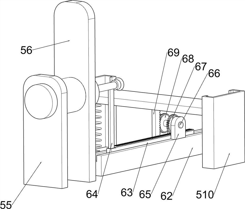
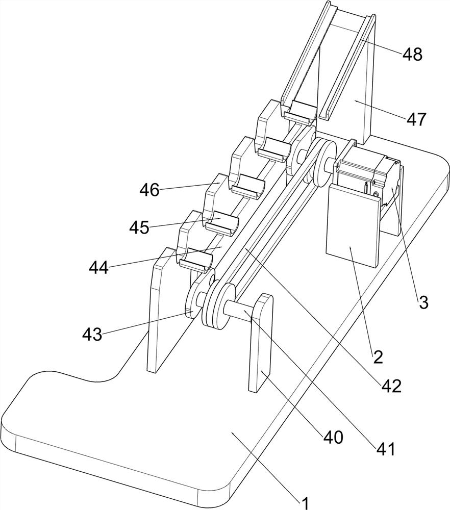
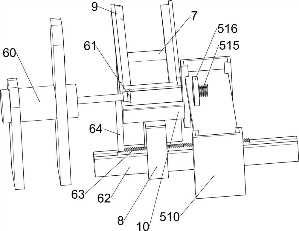
[0022] A device for separating the body and lid of a can, such as figure 1 and Figure 5 As shown, it includes a base 1, a support frame 2, a servo motor 3, a feeding mechanism 4, a cutting mechanism 5, a pushing mechanism 6, a first support block 7, a support member 8, a blanking member 9 and a U-shaped groove 10, and the base 1 The right side of the upper part is provided with a support frame 2, the upper part of the support frame 2 is provided with a servo motor 3, the upper part of the base 1 is provided with a feeding mechanism 4, the upper part of the base 1 is provided with a cutting mechanism 5, the upper part of the base 1 is provided with a pushing mechanism 6, and the upper part of the base 1 is provided with a left The side is provided with a first support block 7, the upper part of the first support block 7 is symmetrically provided with a blanking part 9, the left side of the upper part of the base 1 is provided with a support part 8, the upper part of the suppor...
Embodiment 2
[0025] On the basis of Example 1, such as Figure 2-6 As shown, the feeding mechanism 4 includes a first supporting plate 40, a first connecting shaft 41, a first pulley assembly 42, a rotating block 43, a feeding plate 44, a discharge trough 45, a clamping plate 46, a second supporting plate 47 and a lower Feed trough 48, base 1 upper left front side is provided with first supporting plate 40, and first supporting plate 40 is provided with first connecting shaft 41 in rotation, is connected between the first connecting shaft 41 and the output shaft of servo motor 3 A pulley assembly 42, the first connecting shaft 41 and the output shaft of the servo motor 3 are provided with a rotating block 43, the middle of the upper part of the base 1 is symmetrically provided with clamping plates 46, and the rotating blocks 43 on both sides are provided with feeding plates in a rotating manner 44. The feeding plate 44 is located between the clamping plates 46 on both sides. The upper part...
PUM
 Abstract
Description
Claims
Application Information
 - R&D
- Intellectual Property
- Life Sciences
- Materials
- Tech Scout
- Unparalleled Data Quality
- Higher Quality Content
- 60% Fewer Hallucinations
Browse by: Latest US Patents, China's latest patents, Technical Efficacy Thesaurus, Application Domain, Technology Topic, Popular Technical Reports.
© 2025 PatSnap. All rights reserved.Legal|Privacy policy|Modern Slavery Act Transparency Statement|Sitemap|About US| Contact US: help@patsnap.com


