Product function testing jig

A technology for testing fixtures and product functions, applied in the field of fixtures, can solve problems such as poor working performance of test fixtures, and achieve the effects of convenient functional testing, flexible adjustment, and simple and reasonable structure

Inactive Publication Date: 2020-12-18
苏州润明恩电子科技有限公司
View PDF6 Cites 1 Cited by
  • Summary
  • Abstract
  • Description
  • Claims
  • Application Information

AI Technical Summary

Problems solved by technology

[0005] A product function test fixture proposed by the present invention solves the problem of poor working performance of the test fixture

Method used


Image

  • Product function testing jig
  • Product function testing jig
  • Product function testing jig

Examples


Embodiment Construction

[0022] The following will clearly and completely describe the technical solutions in the embodiments of the present invention with reference to the accompanying drawings in the embodiments of the present invention. Obviously, the described embodiments are only some, not all, embodiments of the present invention.

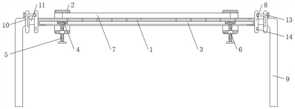
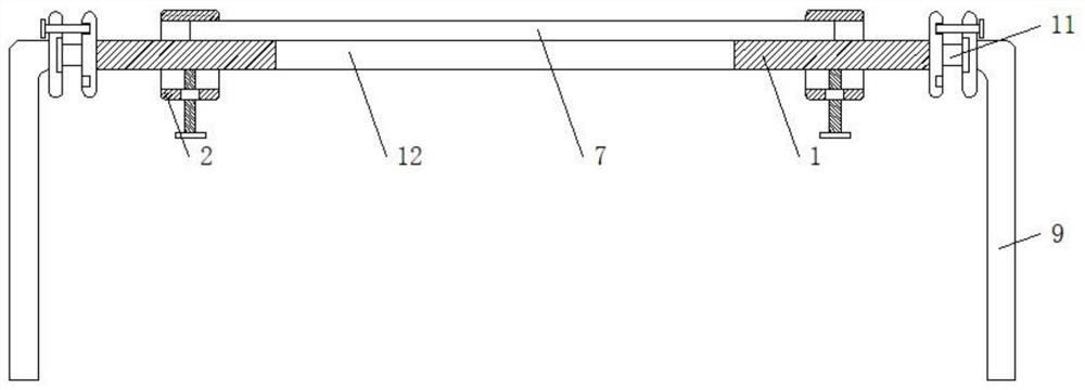
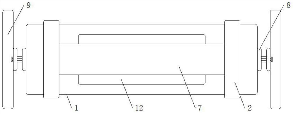
[0023] refer to Figure 1-4 , a product function test fixture, including a workbench 1, both ends of the workbench 1 are provided with support mechanisms, the outside of the two ends of the workbench 1 are slidingly sleeved with a fixed frame 2, and both sides of the bottom of the workbench 1 are provided with There is a chute 3, the two ends inside the chute 3 are slidably connected to the slider 4, the bottom of the slider 4 is connected to the screw 5 through the bearing rotation, and the end of the screw 5 away from the slider 4 extends to the workbench 1 The outer wall of the screw rod 5 located below the workbench 1 is screwed with a drive sleeve 6, and the dri...


PUM


Abstract

The invention discloses a product function testing jig, and relates to the technical field of jigs. Aiming at solving the problem that an existing testing jig is poor in working performance, the following scheme is currently put forwards, specifically, the product function testing jig comprises a workbench, supporting mechanisms are arranged at the two ends of the workbench correspondingly, and fixing frames are slidably arranged at the outer portions of the two ends of the workbench in a sleeving mode correspondingly; and sliding grooves are formed in the two sides of the bottom of the workbench correspondingly, sliding blocks are slidably connected to the two ends of the interiors of the sliding grooves correspondingly, screw rods are rotatably connected to the bottoms of the sliding blocks through bearings correspondingly, the ends, away from the sliding blocks, of the screw rods extend to the lower portion of the workbench, and the positions, on the lower portions of the workbench,of the outer walls of the screw rods are connected with driving sleeves in threaded and sleeved modes. The product function testing jig is simple and reasonable in structure, a user can convenientlyperform function test on a product, the testing jig can be flexibly adjusted, and the product on the testing jig can be simply and conveniently turned over, so that the user can conveniently perform function test on different parts of the product, and the testing jig is high in working performance and convenient to use.

Description

technical field [0001] The invention relates to the technical field of jigs, in particular to a jig for product function testing. Background technique [0002] During the production process of the product, it is necessary to use the corresponding test fixture to clamp and fix the product, so as to facilitate the user to perform functional testing on it. [0003] In the prior art, a Chinese patent document with the authorized publication number CN205825986U and the authorized announcement date of 20161221 discloses a product function test fixture, including a fixture base, and the two sides of the fixture base have product fixing A thimble is provided between the product fixing seats on the jig base, a tray is provided on the product fixing seat, product fixing columns are arranged on both sides of the tray, and a product fixing column is located on the tray. There are through holes for thimbles to pass between the product fixing posts. The product function test fixture pro...

Claims


Application Information

Patent Timeline
Patent Type & Authority Applications(China)
IPC IPC(8): B25B11/00B25H1/08G01M99/00
CPCB25B11/00B25H1/08G01M99/008
Inventor 戚全龙
Owner 苏州润明恩电子科技有限公司
Why Eureka
Try Eureka