A multi-stage swirl combustor with double return flow

A combustion chamber and swirl technology, applied in the combustion chamber, continuous combustion chamber, combustion method, etc., can solve the problems of poor working performance of the combustion chamber, low utilization rate of oxidant, poor mixing performance, etc. The effect of burning out, increasing the temperature, reducing the burning intensity

Active Publication Date: 2017-11-21
INST OF ENGINEERING THERMOPHYSICS - CHINESE ACAD OF SCI
View PDF4 Cites 0 Cited by
  • Summary
  • Abstract
  • Description
  • Claims
  • Application Information

AI Technical Summary

Problems solved by technology

Single-stage swirlers have problems of uneven mixing and poor mixing performance in mixing fuel and oxidant
Inhomogeneous mixing of fuel and oxidizer leads to poor performance of the combustion chamber
In addition, the known combustion chamber of this type adopts a radial double-annular cavity form between the flame cylinder and the combustion chamber wall. The inner annular cavity of this type flows flue gas, and the outer annular cavity flows oxidant. Under this structure , there is no supplementary combustion oxidizer in the combustion chamber, resulting in the problem of low combustion efficiency
There is also a known single-annular cavity form between the flame tube and the combustion chamber wall of this type of combustion chamber. Under this structure, the annular cavity flows oxidant, and a large amount of oxidant is used for mixing at the end of the combustion chamber, causing the combustion chamber to appear The problem of low utilization rate of oxidant

Method used


Image

  • A multi-stage swirl combustor with double return flow
  • A multi-stage swirl combustor with double return flow
  • A multi-stage swirl combustor with double return flow

Examples


Embodiment 1

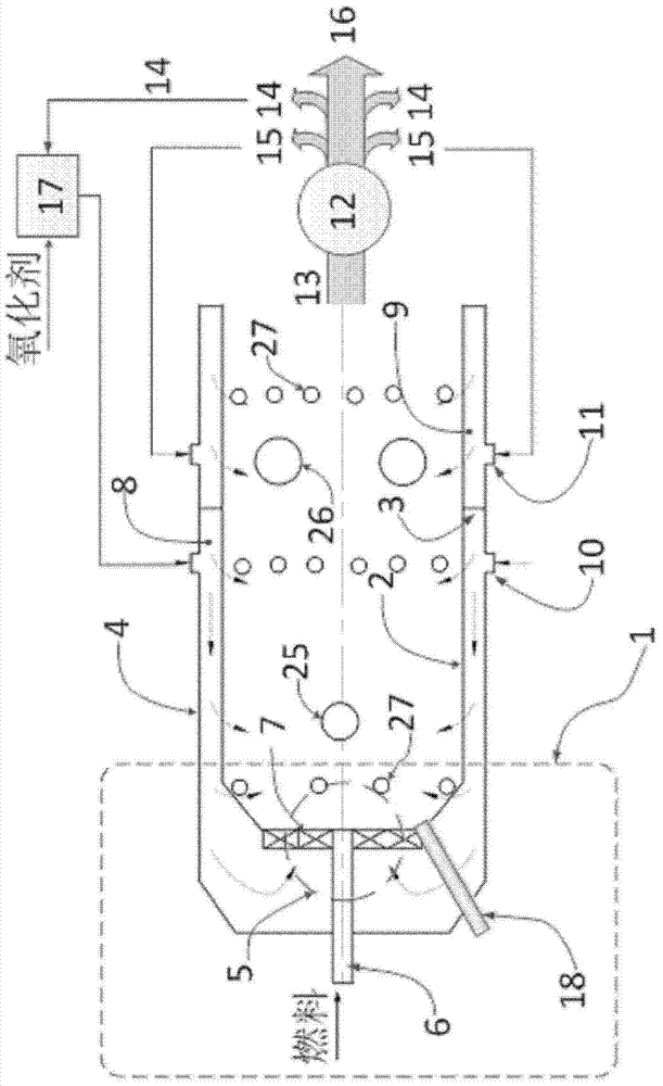
[0033] See figure 1 with figure 2 , The structure of the first embodiment of the present invention is as follows:

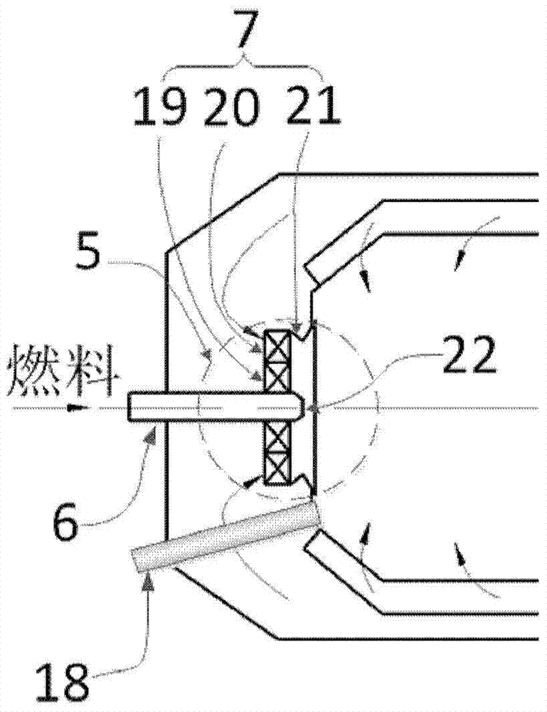
[0034] The combustion chamber has a single tube structure, which is composed of a combustion head 1, a flame tube 2, a baffle 3, a combustion chamber wall 4, a heat exchanger 12 and a mixer 17. The dividing plate 3 divides the annular cavity between the flame tube 2 and the combustion chamber wall 4 into two upstream and downstream annular cavities. The upstream annular cavity of the dividing plate 3 is the first annular cavity 8, and the downstream annular cavity of the dividing plate 3 is The second ring cavity 9. The air inlet of the first ring cavity 8 is the first ring cavity interface 10, and the air inlet of the second ring cavity 9 is the second ring cavity interface 11. The combustion head 1 is composed of a combustor 5. The combustor 5 is composed of a fuel nozzle 6 arranged in the center and a swirler 7 in the outer ring. The fuel nozzle 6 is provided w...

Embodiment 2

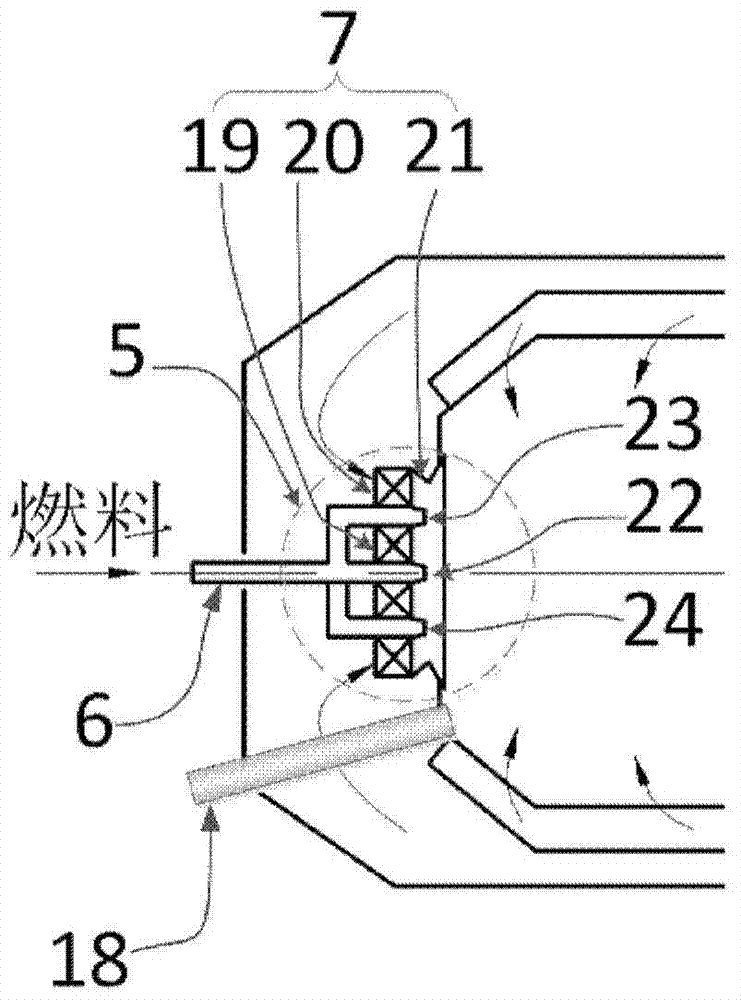
[0037] See figure 1 with image 3 , Is a schematic structural diagram of the second embodiment of the present invention. The difference from the first embodiment is that the fuel nozzle 6 includes a plurality of nozzles, and the fuel nozzles and the swirler are arranged alternately. in image 3 Three fuel nozzles 22, 23, 24 are shown in the middle, and the fuel nozzles 22, 23, 24 and swirlers 19, 20 are arranged alternately. The rest is the same as in Example 1.


PUM


Abstract

A multi-stage swirl combustor with two-way backflow: the combustion head is provided with a fuel nozzle and a plurality of coaxial swirlers radially arranged; the nozzles of the fuel nozzles are arranged alternately with the swirlers; radially adjacent The swirler is arranged in anti-rotation direction; the wall of the flame tube is provided with multiple exhaust holes, and there are two annular cavities, upstream and downstream, connected in series in the axial direction through a partition plate between the flame tube and the wall of the combustion chamber. The annular cavity is the first annular cavity, and the first annular cavity communicates with the inner cavity of the flame tube through the air holes on the wall of the flame tube and the burner of the combustion head. The annular cavity downstream of the flow partition is the second annular cavity, and the second annular cavity passes The air holes on the wall of the flame tube communicate with the inner cavity of the flame tube; the outlet of the flame tube is connected to the heat exchanger through a flue gas pipe, and then respectively connected to the first annular cavity interface, the second annular cavity interface and the downstream of the combustion chamber.

Description

Technical field [0001] The invention relates to the field of submarine power combustion, in particular to a multi-stage swirling combustion chamber with dual-path reflux. Background technique [0002] The combustion head of the well-known submarine power combustion chamber is a single swirl burner, that is, a central fuel nozzle, and a single-stage swirler is provided on the outer ring of the fuel nozzle. The single-stage cyclone has the problems of uneven mixing and poor mixing performance in mixing fuel and oxidizer. The uneven mixing of fuel and oxidant leads to poor performance of the combustion chamber. In addition, the well-known type of combustion chamber adopts a radial double-ring cavity between the flame tube and the wall of the combustion chamber. In this form, flue gas flows in the inner ring cavity and oxidant flows in the outer ring cavity. Under this structure , There is no oxidant for afterburning in the combustion chamber, which leads to the problem of low comb...

Claims


Application Information

Patent Timeline
Patent Type & Authority Patents(China)
IPC IPC(8): F23R3/58F23R3/38F23R3/40
Inventor 曾青华孔文俊赵玮杰杨帆贺红娟艾育华
Owner INST OF ENGINEERING THERMOPHYSICS - CHINESE ACAD OF SCI
Why Eureka
Try Eureka