Adjustable gypsum board water squeezer for gypsum molding
An adjustable, plaster mold technology, applied in the direction of pressing rollers, etc., can solve the problems of destroying gypsum boards, laborious, low work efficiency, etc., and achieve the effect of improving work efficiency
- Summary
- Abstract
- Description
- Claims
- Application Information
AI Technical Summary
Problems solved by technology
Method used
Image
Examples
Embodiment 1
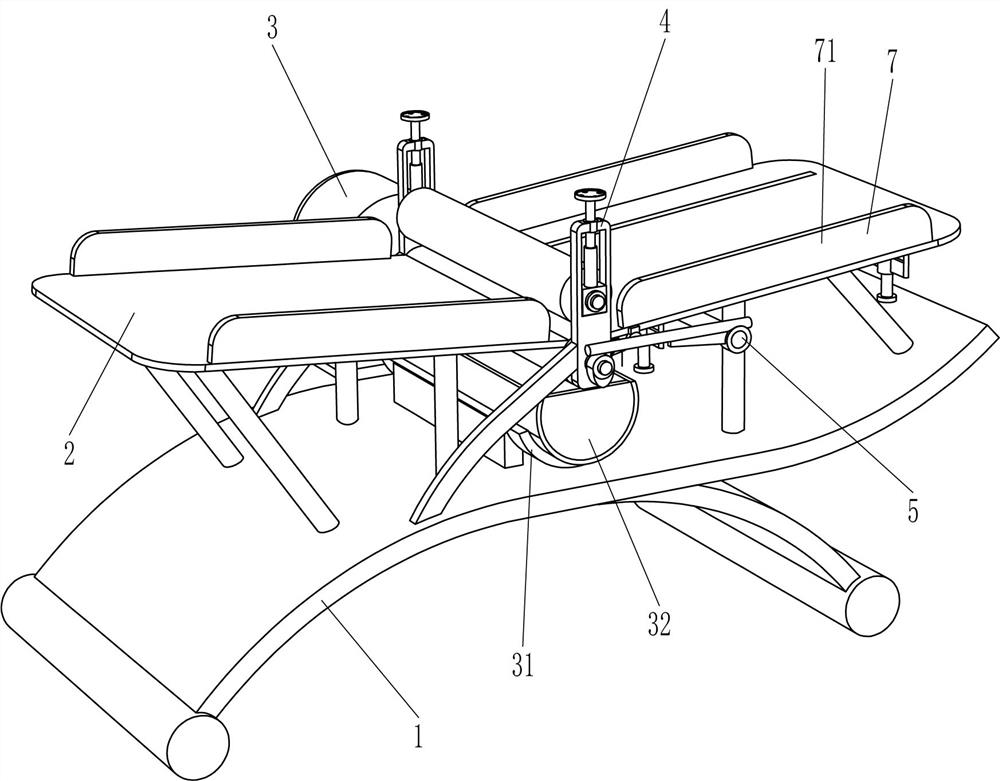
[0048] An adjustable gypsum board water squeezer for gypsum molding, such as figure 1 As shown, it includes a mounting frame 1 , a placing plate 2 and a pressing mechanism 3 . The top of the mounting frame 1 is provided with a placing plate 2 , and the middle of the placing plate 2 is provided with a pressing mechanism 3 .
[0049] When people need to squeeze water on the gypsum board, they only need to put the gypsum board on the right side of the placing board 2. Since the right side of the placing board 2 is inclined, the gypsum board will slide to the left. When the gypsum board passes through the pressing mechanism 3, the extrusion mechanism 3 will squeeze water on the gypsum board. After the gypsum board is squeezed, the gypsum board can be removed from the left side of the placing board 2.
Embodiment 2
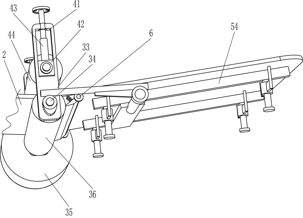
[0051] On the basis of Example 1, as Figure 2-3 As shown, the extrusion mechanism 3 includes a magnet slot 31, an iron basin 32, a fixed plate 33, a rotating shaft 34, a deceleration motor 35 and a roller 36, and a magnet slot 31 is arranged in the middle of the mounting frame 1, and an iron basin 32 is arranged on the magnet slot 31. , the middle of the top of the mounting frame 1 is provided with a fixed plate 33 on both sides, the lower part and the middle of the fixed plate 33 on the front and rear sides are rotatably provided with a rotating shaft 34, and the rear side of the mounting frame 1 is provided with a deceleration motor 35. The output shaft of the motor 35 is connected with the rotating shaft 34 , the rotating shaft 34 is provided with a roller 36 , and the roller 36 is located directly above the iron basin 32 .
[0052] When people need to squeeze water on the gypsum board, they only need to put the gypsum board on the right side of the placing board 2. Since ...
Embodiment 3
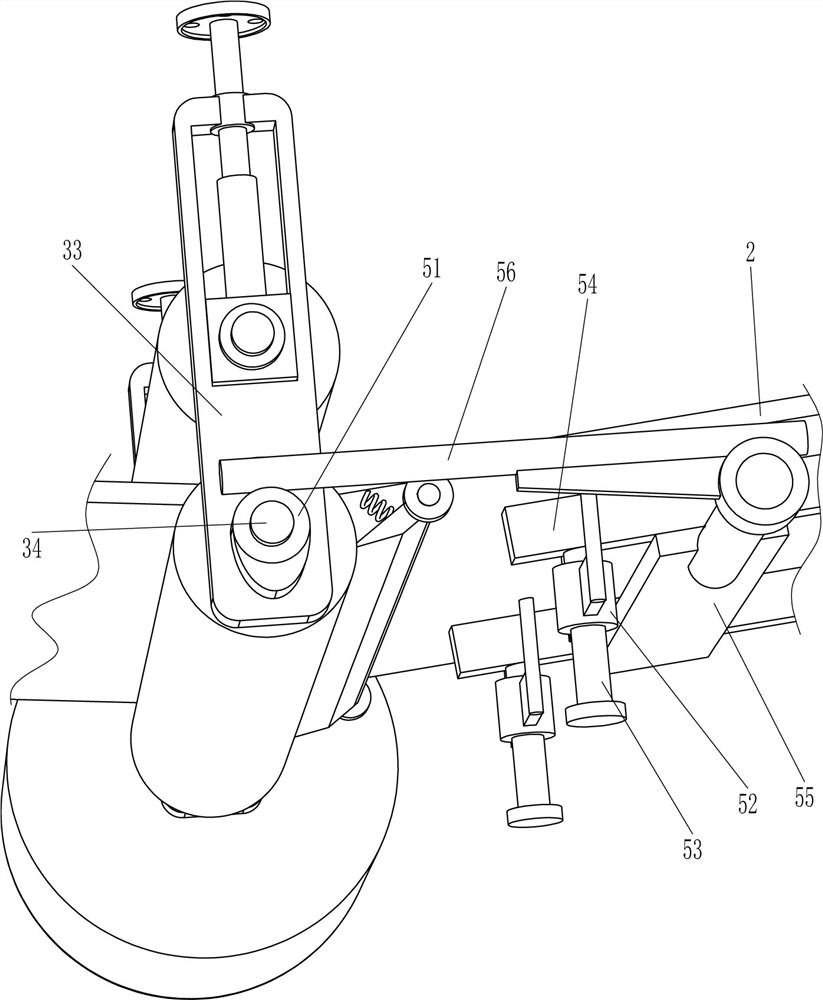
[0056] On the basis of Example 2, as figure 1 , 4 As shown in and 5, a separation mechanism 5 is also included. The separation mechanism 5 includes a cam 51, a sliding sleeve 52, a sliding rod 53, a push plate 54, a connecting plate 55 and a contact rod 56. The front side of the lower shaft 34 is provided with a cam 51. The cam 51 is on the outer side of the fixed plate 33. The front and rear sides of the bottom right side of the placing plate 2 are symmetrically provided with sliding sleeves 52. The number of the sliding sleeves 52 is 4. A push plate 54 is connected between the tops of the two sliding bars 53 on the side and between the tops of the two sliding bars 53 on the rear side. The push plates 54 are slidably connected to the placing plate 2. There is a connecting plate 55 in between, the connecting plate 55 is on the right side of the two sliding sleeves 52 on the left side, and a contact rod 56 is provided on the top of the front side of the connecting plate 55 , a...
PUM
 Abstract
Description
Claims
Application Information
 - R&D
- Intellectual Property
- Life Sciences
- Materials
- Tech Scout
- Unparalleled Data Quality
- Higher Quality Content
- 60% Fewer Hallucinations
Browse by: Latest US Patents, China's latest patents, Technical Efficacy Thesaurus, Application Domain, Technology Topic, Popular Technical Reports.
© 2025 PatSnap. All rights reserved.Legal|Privacy policy|Modern Slavery Act Transparency Statement|Sitemap|About US| Contact US: help@patsnap.com


