Cable sealing cap semi-finished product reciprocating manufacturing machine
A technology for manufacturing machines and semi-finished products, which is applied in the field of reciprocating manufacturing machines for semi-finished cable caps, which can solve the problems of hidden safety hazards for operators, high labor costs, and high requirements, and achieve the effects of improving production efficiency, saving manpower and material resources, and improving safety.
- Summary
- Abstract
- Description
- Claims
- Application Information
AI Technical Summary
Problems solved by technology
Method used
Image

Examples
Embodiment Construction
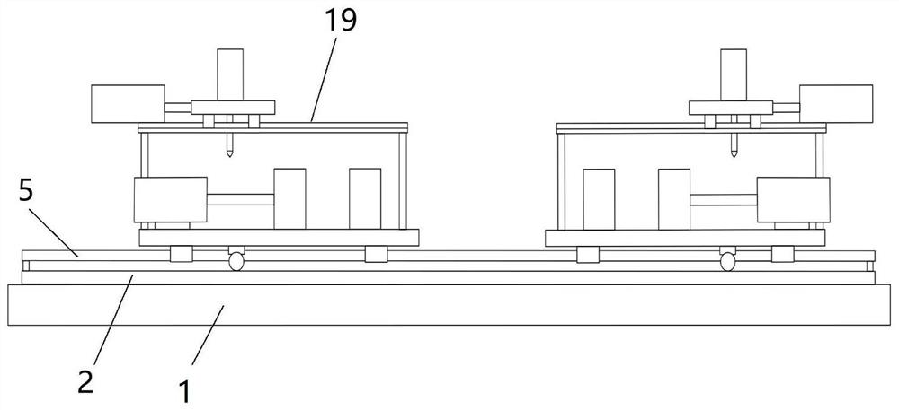
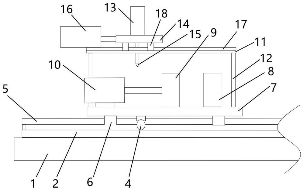
[0019] The embodiment of the present invention discloses a reciprocating manufacturing machine for semi-finished cable caps, including a base 1 and two reciprocating mechanisms 19, two gear guide rails 2 distributed in parallel on both sides of the top of the base 1, and the two reciprocating mechanisms 19 along the gears. The length direction of the guide rail 2 is arranged symmetrically, and two reciprocating mechanisms 19 move along the gear guide rail 2 under the action of the driving mechanism. The reciprocating mechanism 19 includes a mounting plate 7, a first mold 8, a second mold 9, a first cylinder 10, and a support plate 11 , the second cylinder 13, the fixed plate 14 and the gas nozzle 15, the mounting plate 7 reciprocates along the gear guide rail 2 through the drive mechanism, the first mold 8 is fixedly installed on one side of the top of the mounting plate 7, and the other side of the top of the mounting plate 7 is fixed with The first cylinder 10, the telescopic...
PUM
 Abstract
Description
Claims
Application Information
PatSnap Eureka turns technology decisions into work you can execute. Powered by our Innovation Knowledge Graph, it runs expert workflows across engineering, life sciences, materials and intellectual property. Get your review-ready output in minutes.


