Mixing structure for liquid rocket engine

A hybrid structure and liquid rocket technology, which is applied in the direction of rocket engine devices, machines/engines, mechanical equipment, etc., can solve problems affecting the reliability of the thrust chamber structure, achieve full contact heat transfer, ensure temperature uniformity and stability, The effect of reducing adverse effects

Pending Publication Date: 2020-12-18
AEROSPACE SCI & IND KET TECH CO LTD
View PDF0 Cites 0 Cited by
  • Summary
  • Abstract
  • Description
  • Claims
  • Application Information

AI Technical Summary

Problems solved by technology

[0003] The invention provides a hybrid structure for a liquid rocket engine, which solves the technical problem in the prior art that the regenerative cooling hybrid structure of a methane engine affects the structural reliability of a thrust chamber

Method used


Image

  • Mixing structure for liquid rocket engine
  • Mixing structure for liquid rocket engine
  • Mixing structure for liquid rocket engine

Examples


Embodiment Construction

[0019] The embodiment of the present application provides a hybrid structure for a liquid rocket engine to solve the technical problem in the prior art that the regenerative cooling hybrid structure of a methane engine affects the structural reliability of the thrust chamber.

[0020] In order to better understand the above technical solutions, the above technical solutions will be described in detail below in conjunction with the accompanying drawings and specific implementation methods. It should be understood that the embodiments of the present invention and the specific features in the embodiments are detailed descriptions of the technical solutions of the present application. , rather than limiting the technical solutions of the present application, the embodiments of the present application and the technical features in the embodiments can be combined without conflict.

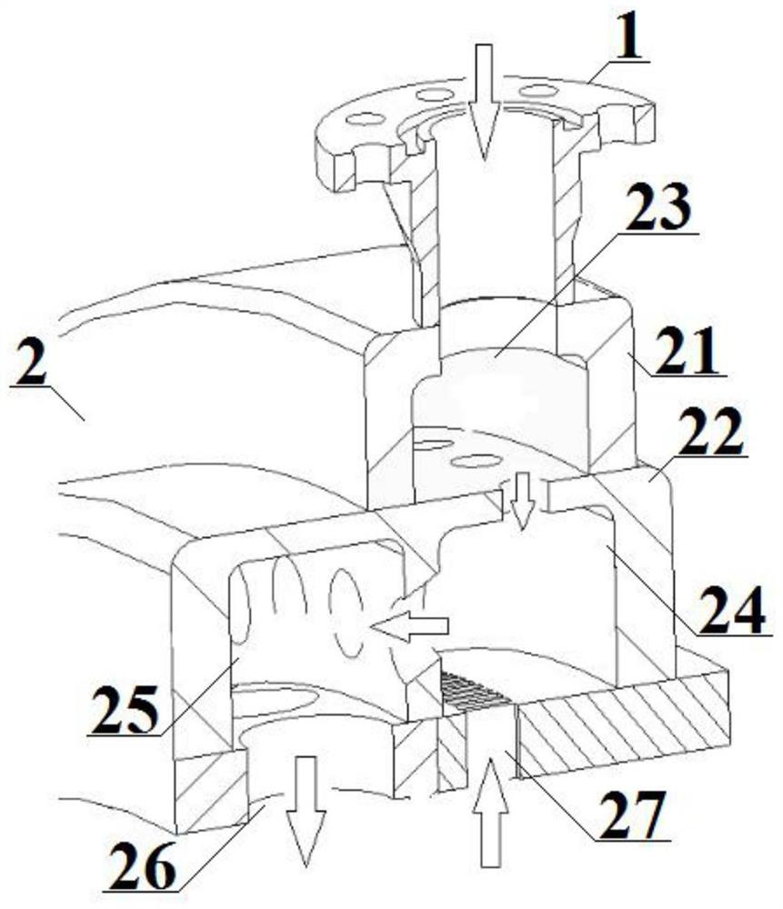
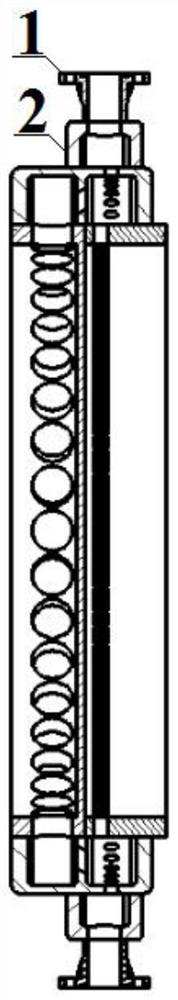
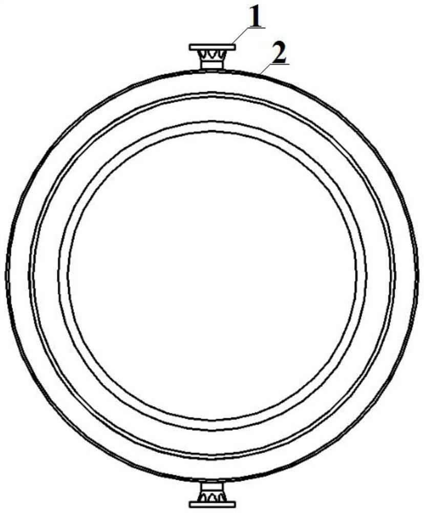
[0021] see figure 1 , figure 2 and image 3 , a mixing structure for a liquid rocket engine, compr...


PUM


Abstract

The invention belongs to the technical field of liquid engine cooling, and discloses a mixing structure for a liquid rocket engine. The mixing structure comprises an annular mixing box body and a high-temperature air inlet box body, the annular mixing box body is divided into a second air cavity and a third air cavity which are adjacently arranged in the axial direction of the annular mixing box body through a partition plate arranged in the annular mixing box body; a second air inlet is formed in the second air cavity, and an air outlet is formed in the third air cavity; a second guide flow channel is formed in the partition plate and communicates with the second air cavity and the third air cavity; the high-temperature air inlet box body is fixed to the top of the annular mixing box bodyin the radial direction of the annular mixing box body and communicates with the second air cavity through a first guide flow channel formed in the second air cavity, and a first air inlet is formedin the high-temperature air inlet box body; and the first guide flow channel is opposite to the second air inlet. The mixing structure for the liquid rocket engine can prevent the mixing device from degrading the structural strength of a thrust chamber.

Description

technical field [0001] The invention relates to the technical field of liquid engine cooling, in particular to a hybrid structure for liquid rocket engines. Background technique [0002] Regenerative cooling is one of the most widely used thermal protection technologies for liquid rocket engine thrust chambers. For liquid oxygen methane engines, a two-way or multi-way regenerative cooling structure is adopted; the mixing of returning methane gas working fluid before returning to the head cavity generally requires at least three Chamber: collection chamber for high-temperature gas, mixing chamber for mixing high-temperature gas and low-temperature gas, and collection chamber for further mixing and uniform flow of mixed gas. In the prior art, the three cavities are arranged in sequence along the axial direction, and the overall span of the hybrid structure is relatively large in the axial direction. In order to adapt to the high engine room pressure and ensure the structural s...

Claims


Application Information

Patent Timeline
Patent Type & Authority Applications(China)
IPC IPC(8): F02K9/64
CPCF02K9/64
Inventor 刘鑫鹏姬威信王弘亚邵艳刘岳高翔杨跃姚少君
Owner AEROSPACE SCI & IND KET TECH CO LTD
Why Eureka
Try Eureka