Mechanical touch switch for faucet and water-saving method for controlling water flow
A touch switch, faucet technology, applied in mechanical equipment, separation methods, chemical instruments and methods, etc., can solve the problems of poor water flow controllability, inconvenient water flow, power consumption and other problems, achieve energy saving and water saving installation, easy installation, reduce The effect of production costs
- Summary
- Abstract
- Description
- Claims
- Application Information
AI Technical Summary
Problems solved by technology
Method used
Image

Examples
Embodiment 1
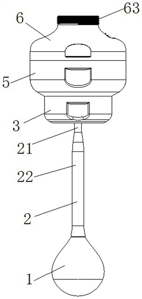
[0046] Mechanical tactile switches for faucets, combined with Figure 1 to Figure 10 As shown, it includes a switch cavity, a connecting rod 2, a water-proof control board 7 and a touch head 1.
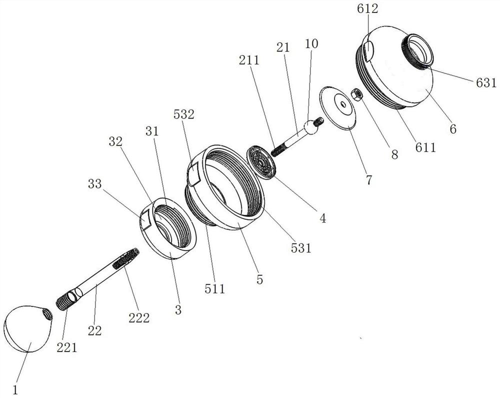
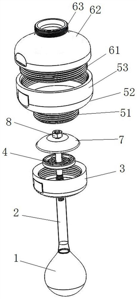
[0047] The inside of the switch cavity is hollow and the top is detachably connected with the faucet. The switch chamber includes a lower control chamber 5 and an upper control chamber 6 that are detachably connected. The bottom end of the lower control chamber 5 is detachably connected with a nozzle 3 , and the connecting rod 2 moves through the nozzle 3 .
[0048] The lower control chamber 5 is used to control the waterway switch and the size of the flow rate. The lower control chamber 5 includes a bottom columnar cavity 51 , a tapered cavity 52 and a top columnar cavity 53 integrally connected. A first external thread 511 is provided on the outer wall of the bottom columnar cavity 51 , and a second internal thread 531 is provided on the inner wall of the top columnar cavity 53 . Th...
Embodiment 2
[0066] Based on the basis of the present embodiment 1, the present embodiment is a water-saving method for controlling the water flow. The method is based on a mechanical touch switch for a faucet, and includes the following steps:
[0067] S1. Push the touch head 1 upward under the action of external force, the touch head 1 drives the connecting rod 2 and the water-proof control plate 7 to move upward, the water-proof control plate 7 is separated from the inner wall of the tapered cavity 52 controlling the lower cavity 5, and the waterway is opened. A water outlet is formed between the water-proof control panel 7 and the conical cavity 52 of the lower control cavity 5, that is, the mechanical touch switch is turned on.
[0068] After the water flow enters the switch cavity from the faucet, it enters the nozzle 3 from the water outlet, and is buffered by the foaming filter 4 before being discharged.
[0069] S2. Control the size of the water outlet by pushing up the degree of ...
Embodiment 3
[0072] Based on the basis of the present embodiment 1, the present embodiment is a water-saving method for controlling the water flow. The method is based on a mechanical touch switch for a faucet, and includes the following steps:
[0073] S10. Move the touch head 1 along a horizontal direction under the action of an external force, and the touch head 1 drives the connecting rod 2 and the water-proof control plate 7 to move horizontally in this direction, and the water-proof control plate 7 and the tapered cavity 52 of the lower cavity 5 are controlled Stagger between them to form a water outlet gap, that is, the mechanical touch switch is turned on. When moving horizontally, it can move in any direction along the horizontal plane.
[0074] S20. Control the size of the water outlet gap by adjusting the horizontal movement of the touch head 1, the connecting rod 2, and the water barrier control plate 7 in step S10, that is, the size of the water outlet gap can be controlled ac...
PUM
 Abstract
Description
Claims
Application Information
 - R&D
- Intellectual Property
- Life Sciences
- Materials
- Tech Scout
- Unparalleled Data Quality
- Higher Quality Content
- 60% Fewer Hallucinations
Browse by: Latest US Patents, China's latest patents, Technical Efficacy Thesaurus, Application Domain, Technology Topic, Popular Technical Reports.
© 2025 PatSnap. All rights reserved.Legal|Privacy policy|Modern Slavery Act Transparency Statement|Sitemap|About US| Contact US: help@patsnap.com