Multi-angle heat dissipation power distribution cabinet

A multi-angle, power distribution cabinet technology, applied in the substation/power distribution device shell, electrical components, cleaning methods using tools, etc., can solve the problems of small heat dissipation range and poor effect, achieve good shock absorption effect, and expand heat dissipation The effect of improving the range and damping performance

Inactive Publication Date: 2020-12-18
张希刚
View PDF0 Cites 9 Cited by
  • Summary
  • Abstract
  • Description
  • Claims
  • Application Information

AI Technical Summary

Problems solved by technology

[0003] When the components in the power distribution cabinet work, they will generate heat, so heat dissipation is required. The existing power distribution cabinets generally use fixedly installed fans to dissipate heat. The heat dissipation range is small and the effect is poor.

Method used


Image

  • Multi-angle heat dissipation power distribution cabinet
  • Multi-angle heat dissipation power distribution cabinet
  • Multi-angle heat dissipation power distribution cabinet

Examples


Embodiment 1

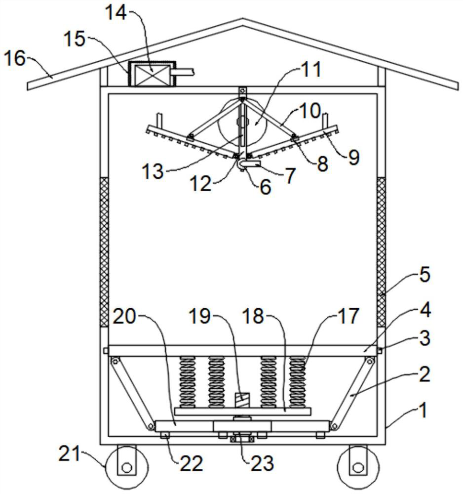
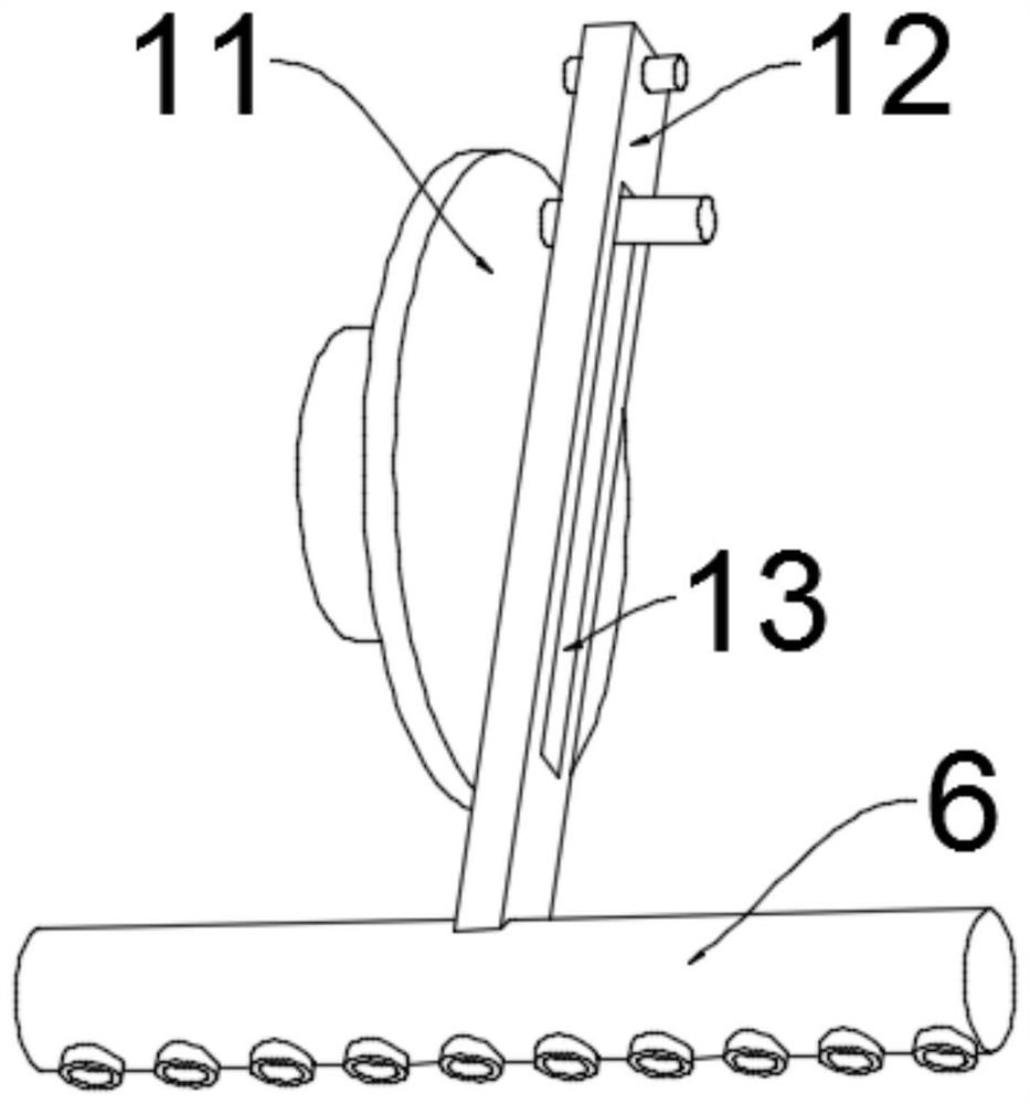
[0023] see Figure 1~2 , in an embodiment of the present invention, a power distribution cabinet for multi-angle heat dissipation, including a cabinet body 1 and a heat dissipation unit for cooling components in the cabinet body 1, universal wheels 21 are evenly and symmetrically installed on the bottom of the cabinet body 1, and the cabinet body is convenient To move the body 1, a cabinet door is installed on the front side wall of the cabinet body 1. In this embodiment, the cabinet door is preferably connected to the cabinet body 1 through hinges and hasps, and ventilation nets are installed on both side walls of the cabinet body 1. 5. In this embodiment, the ventilation net 5 is preferably connected to the cabinet body 1 through screws, and a rain shield 16 is fixedly installed on the top of the cabinet body 1. The rain shield 16 is preferably in the shape of an umbrella, and the heat dissipation unit includes a second A motor, a turntable 11, a movable rod 12, a heat dissi...

Embodiment 2

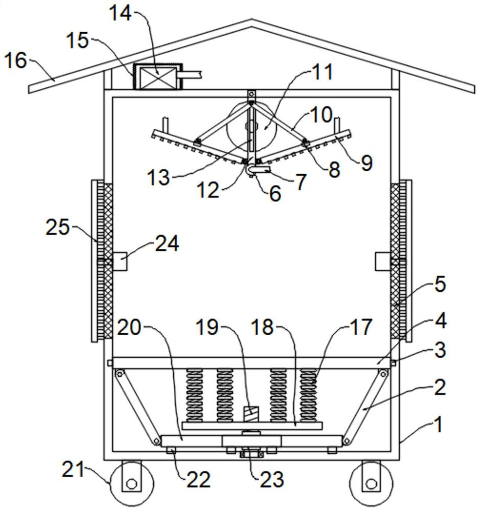
[0026] see image 3 The difference between this embodiment of the present invention and Embodiment 1 is that in order to prevent the ventilation net 5 from being blocked by dust, a second motor 24 is fixedly installed on the ventilation net 5 in the cabinet body 1, and the output shaft of the second motor 24 Through the ventilation net 5 and extended to the outside of the ventilation net 5, the end of the output shaft of the second motor 24 is fixed by the brush bar 25, and the second motor 24 drives the brush bar 25 to rotate, and the ventilation net 5 is brushed. The blowing of 9 plays a good cleaning effect on the ventilation net 5, which helps to dissipate heat and ventilate.

[0027] The working principle of the present invention is: when working, the heat dissipation fan 14 sends air into the heat dissipation plate 9 and the heat dissipation pipe 6, and is sprayed out by the nozzle to cool the components by air. At the same time, the first motor drives the turntable 11 t...


PUM


Abstract

The invention discloses a multi-angle heat dissipation power distribution cabinet, which relates to the technical field of power equipment, and mainly aims to solve the problem of poor heat dissipation effect of an existing power distribution cabinet. The cabinet comprises a cabinet body and a heat dissipation unit used for dissipating heat of elements in the cabinet body, ventilation nets are installed on the two side walls of the cabinet body, the heat dissipation unit comprises a first motor, a rotary disc, a movable rod, a heat dissipation pipe, a first connecting rod and a heat dissipation plate, and an installation plate used for installing the elements is installed on the lower portion of an inner cavity of the cabinet body in a sliding mode; a damping unit is connected between theinstallation plate and the bottom of the cabinet body, the damping unit comprises a second connecting rod, a rack, a gear, a threaded rod, a supporting plate and a damping spring, a heat dissipation unit is arranged to drive a heat dissipation plate and a heat dissipation pipe to swing around the top end of a movable rod, the heat dissipation angle is continuously changed, and the heat dissipationrange is expanded. The heat dissipation plate is driven by the first connecting rod to swing around the end connected with the movable rod, so that the heat dissipation angle of the heat dissipationplate is further continuously changed; and the damping units are arranged, so that the damping effect is better.

Description

technical field [0001] The invention relates to the technical field of electric equipment, in particular to a power distribution cabinet with multi-angle heat dissipation. Background technique [0002] Power distribution cabinets (boxes) are divided into power distribution cabinets (boxes), lighting distribution cabinets (boxes), and metering cabinets (boxes), which are the final equipment of the power distribution system. The power distribution cabinet is a general term for the motor control center. The power distribution cabinet is used in the occasions where the load is relatively scattered and there are few circuits; the motor control center is used in the occasions where the load is concentrated and there are many circuits. They distribute the electric energy of a certain circuit of the upper-level power distribution equipment to the nearest load. This level of equipment shall provide protection, monitoring and control of the load. [0003] When the components in the...

Claims


Application Information

Patent Timeline
Patent Type & Authority Applications(China)
IPC IPC(8): H02B1/56H02B1/30H02B1/28H02B1/52H02B1/54F16F15/067B08B1/00B08B1/04
CPCB08B1/002B08B1/04F16F15/067H02B1/28H02B1/30H02B1/52H02B1/54H02B1/56
Inventor 张希刚
Owner 张希刚
Why Eureka
Try Eureka