
Motor rotor

A technology of motor rotor and rotor iron core, applied in electric components, electrical components, electromechanical devices, etc., can solve the problems of poor braking effect and insufficient clamping stability, achieve easy automatic braking, improve braking effect, guarantee The effect of stability

Pending Publication Date: 2020-12-18
苏州佳电飞球电机有限公司
View PDF1 Cites 1 Cited by
  • Summary
  • Abstract
  • Description
  • Claims
  • Application Information

AI Technical Summary

Problems solved by technology

When the conical motor is braking, the clamping connection is not stable enough, resulting in poor braking effect

Method used


Image

  • Motor rotor
  • Motor rotor
  • Motor rotor

Examples


Embodiment Construction

[0019] The following will clearly and completely describe the technical solutions in the embodiments of the present invention with reference to the accompanying drawings in the embodiments of the present invention. Obviously, the described embodiments are only some, not all, embodiments of the present invention.

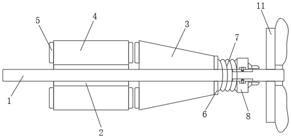
[0020] refer to Figure 1-Figure 6 , a motor rotor, comprising a shaft main body 1, a reinforcement area 2 disposed outside the shaft body 1, a conical rotor core 3 disposed outside the shaft body 1, and a circular rotor core 4 disposed outside the reinforcement area 2.

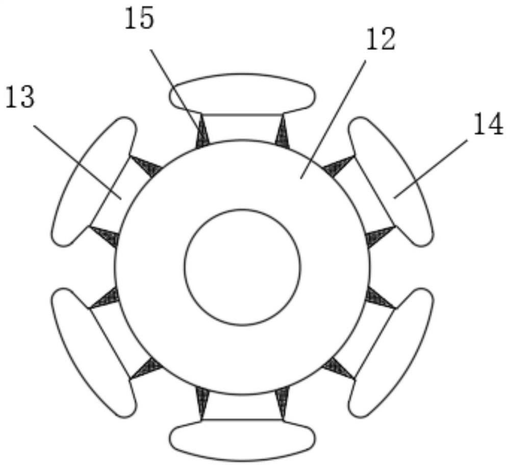
[0021] see figure 2 , the circular rotor core 4 includes a swivel 12, the inner wall of the swivel 12 is connected to the reinforcement area 2, the side wall of the swivel 12 is connected with a plurality of fixed blocks 13, and the side walls of the plurality of fixed blocks 13 are connected with external blocks 14. The side walls on both sides of the external block 14 are provided with chamfers,...


PUM


Abstract

The invention relates to a motor rotor. The motor rotor comprises a rotating shaft main body, the rotating shaft main body is provided with a conical rotor iron core and a circular rotor iron core, the side wall, away from the circular rotor iron core, of the conical rotor iron core is fixedly connected with a spring clamping seat, the side wall of the spring clamping seat is connected with a movable ring through a spring, and the inner wall of the movable ring is slidably connected with the side wall of the rotating shaft main body. The side wall of the movable ring is fixedly connected withan annular circular truncated cone, the side wall of the annular circular truncated cone is fixedly connected with a plurality of clamping columns, the clamping columns are arranged in an annular array with the axis of the annular circular truncated cone as the center, and the rotating shaft main body is fixedly sleeved with a fan brake wheel. By utilizing the combination of the conical rotor ironcore and the circular rotor iron core, a good brake limiting effect can be achieved, air gaps are reduced, the electric energy utilization rate is improved, and meanwhile, the stability of the motorduring braking can be greatly improved by utilizing the matching of the clamping columns and limiting rings.

Description

technical field [0001] The invention relates to the technical field of motors, in particular to a motor rotor. Background technique [0002] Electric machines generally include a stator and a rotor, the rotor being rotatably mounted to the stator. The rotor includes a shaft, a rotor core fixed to the shaft, and a commutator. The rotor core has a number of radially protruding teeth, and winding slots are formed between adjacent teeth for accommodating coil windings, and the number of teeth of the rotor is equal to the number of winding slots. In the prior art, the conical motor has a large air gap and low power utilization rate, and the conical rotor is large in size and heavy in weight, which puts great pressure on the rotating shaft, resulting in a short service life of the entire motor. [0003] The Chinese patent whose publication number is CN2585475Y discloses a conical motor, which is mainly composed of a stator, a conical rotor, a compression spring, a fan brake whee...

Claims


Application Information

Patent Timeline
IPC IPC(8): H02K1/22H02K7/12
CPCH02K1/22H02K7/12
Inventor 李雪东李彦鹏杨光
Owner 苏州佳电飞球电机有限公司
Features
  • Generate Ideas
  • Intellectual Property
  • Life Sciences
  • Materials
  • Tech Scout
  • Unparalleled Data Quality
  • Higher Quality Content
  • 60% Fewer Hallucinations
Learn More