Capacitor conveying assembly line

An assembly line and capacitor technology, applied in electrical components, electrical components, etc., can solve the problems of large soft extrusion loss of pin quality, static leakage of pin rods, unqualified pins, etc., to improve the safe storage of terminal stacking materials. Effect, guarantee the effect of quality adjustment

Active Publication Date: 2020-12-18
徐州势甲信息科技有限公司
View PDF10 Cites 2 Cited by
  • Summary
  • Abstract
  • Description
  • Claims
  • Application Information

AI Technical Summary

Problems solved by technology

[0004] Aiming at the deficiencies in the prior art, the purpose of the present invention is to provide a capacitor conveying line to solve the problem that the double-pin positive and negative poles of the capacitor column block will cause problems in the conveying line due to the amount of stacking and the soft texture of the pins. The pin bar of the capacitor column is squeezed to cause the deformation of the straight end, which leads to the need to straighten the pin bar when the subsequent capacitor block is plugged into the circuit board, resulting in the inclination of the insertion end of the subsequent pin, which interferes with the normal operation of the capacitor, resulting in subsequent Conveyor belts transport continuous batches of capacitor pins that are unqualified and require secondary trimming and processing operations, and the pins are soft and have a large loss of extrusion, which is easy to rub, collide and slip off the plating layer of the pins, resulting in a safety hazard of static electricity leakage from the pin rods.

Method used


Image

  • Capacitor conveying assembly line
  • Capacitor conveying assembly line
  • Capacitor conveying assembly line

Examples


Embodiment 1

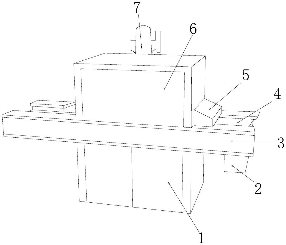
[0032] see Figure 1-Figure 6, the present invention provides a capacitor conveying line, the structure of which includes: a power distribution base box 1, a pin clamp stacking groove 2, a roller side frame plate 3, a conveyor belt 4, a counterweight block 5, and an assembly line cover 6. The cylinder groove 7, the pin clamping stack groove 2 is inserted in the lower right corner of the conveyor belt 4 and is perpendicular to each other, the power distribution base box 1 is nested under the bottom of the assembly line cover 6 and is in the same On the vertical plane, the column groove 7 is inserted on the top of the assembly line cover 6 and is on the same vertical plane, and the counterweight pressing block 5 is close to the lower right corner of the assembly line cover 6 and is on the same vertical plane. On the straight face, there are two roller side frame plates 3 and they are respectively nested on the front and back sides of the conveyor belt 4. The top surface of the ...

Embodiment 2

[0038] see Figure 1-Figure 6 , the present invention provides a pipeline for conveying capacitors, the other aspects are the same as in Embodiment 1, the difference is that:

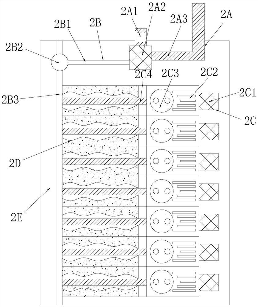
[0039] see figure 2 The storage tank seat 2C is composed of an arc top support rod block 2C1, a ventilating slot seat 2C2, a side-mounted suction cup 2C3, and an electroplating ring rod 2C4. The electroplating ring rod 2C4 is inserted on the left side of the side-mounted suction cup 2C3. The above-mentioned side-attached suction cup 2C3 and the arc-top support rod block 2C1 are respectively closely attached to the left and right sides of the air-permeable slot seat 2C2 and are on the same vertical plane, and the side-positioned arc-top support rod block 2C1 presses the side-attached suction cup 2C3 to form compressed air. The close-to-pad protective clamping effect when the suction capacitor is stored.

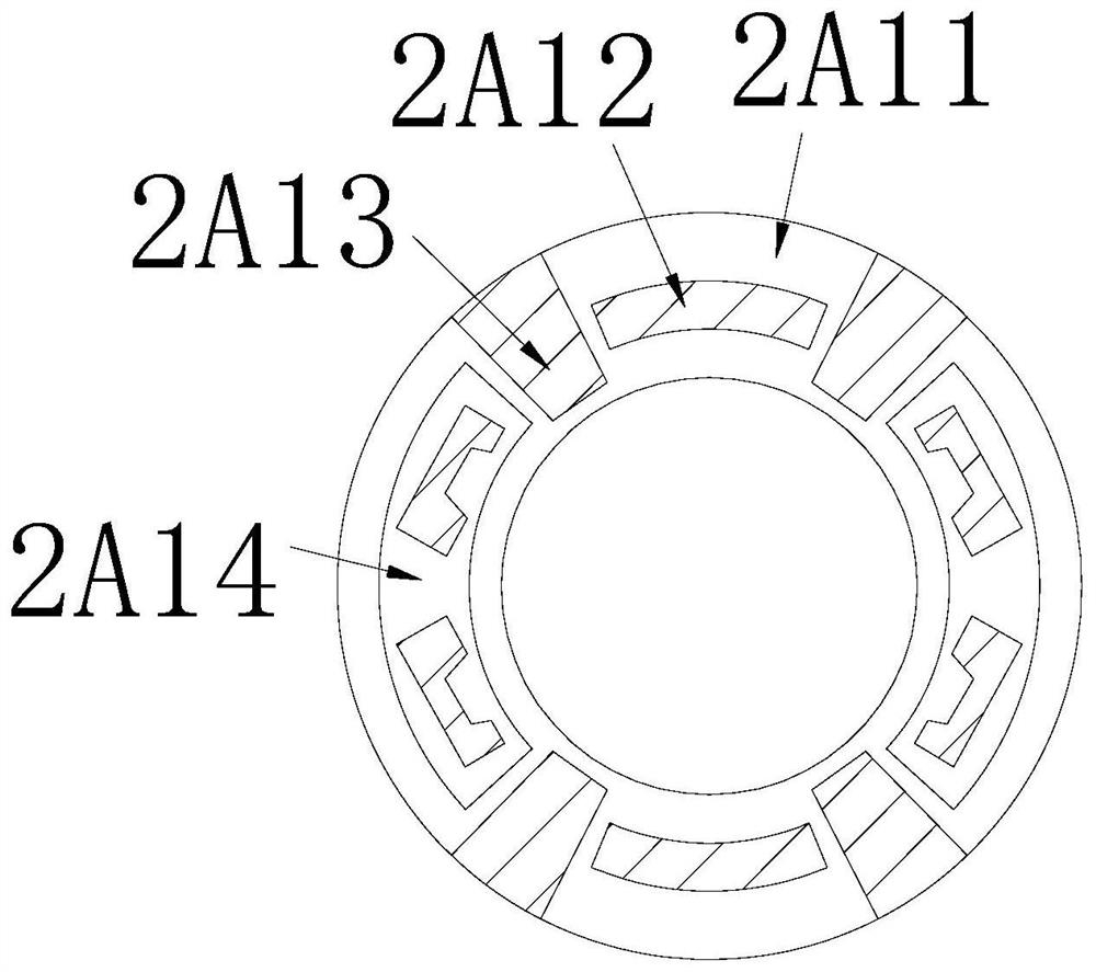
[0040] see Figure 5 , the arc top pole block 2C1 is composed of a double pole ear plate 2C11, a...


PUM


Abstract

The invention discloses a capacitor conveying assembly line which structurally comprises a power distribution base box, a pin clamping and stacking groove, a roller side frame plate, a conveying belt,a counterweight pressing block, an assembly line housing and a column casing groove. The invention discloses a capacitor conveying assembly line which structurally comprises a power distribution basebox, a pin clamping and stacking groove, a roller side frame plate, a conveying belt, a counterweight pressing block, an assembly line housing and a column casing groove. The cooperation of the pin clamping and stacking groove and the conveying belt is realized. A corrugated sleeve and a square barrel groove body are erected at an output end groove through the conveying belt to be matched with acapacitor block to allow the capacitor block to be clamped, settled and stored, the effect of protecting pins by a stacking frame to store capacitors is achieved, paint removal and deformation of thepins are reduced, linear settling sliding installation is conducted through a magnetic ring buckle frame base and a sliding ball support, and then a storage groove base is matched with electromagnetism for exchange of electroplating pin rods. An integral assembly line conveying subsequent automatic trimming effect is formed, the pretreatment secondary pin maintenance effect before the capacitors are conveyed, mounted and welded on a circuit board is guaranteed, electrostatic leakage is prevented, the pin conduction quality and the inner column end adaptive correction effect are improved, and efficient quality adjustment of the internal structure of the capacitor is guaranteed; and the terminal stacking safety storage effect of the conveying assembly line is improved.

Description

technical field [0001] The invention relates to a capacitor conveying assembly line, which belongs to the field of electron conveying. Background technique [0002] The contact of the capacitor block on the circuit board requires two pins to form the current conduction of the positive and negative current flow to adapt to the grid operation, and the electronic components of the capacitor block are transported on the assembly line to carry out the material transportation effect of the rubber insulated conveyor belt to ensure the follow-up electronics. The storage operation effect of component classification and placement, the shortcomings of the current technology to be optimized are: [0003] The two-pin positive and negative terminals of the capacitor block will be piled up and the pins are soft in the conveying line, causing the capacitor block to squeeze the pin rod and cause the straight end to deform, resulting in the subsequent plugging of the capacitor block in the ci...

Claims


Application Information

Patent Timeline
Patent Type & Authority Applications(China)
IPC IPC(8): H05K13/04
CPCH05K13/0419H05K13/04
Inventor 黄选来
Owner 徐州势甲信息科技有限公司
Why Eureka
Try Eureka