Multiplexer

A multiplexer and filter technology, applied in the field of multiplexers, can solve the problems of variable attenuation frequency band, no filter circuit, and large-scale circuit.

Active Publication Date: 2020-12-18
MURATA MFG CO LTD
View PDF15 Cites 0 Cited by
  • Summary
  • Abstract
  • Description
  • Claims
  • Application Information

AI Technical Summary

Problems solved by technology

[0007] However, in conventional filter circuits, it is necessary to provide a signal path having a phase opposite to that of an unwanted signal passing through the filter section separately from the filter section, resulting in an increase in circuit size.
In addition, in a multiplexer applied to CA, frequency characteristics for obtaining optimum circuit characteristics vary depending on the presence or absence of CA and the combination of frequency bands used by CA, but conventional filter circuits do not have Structure with variable attenuation band

Method used


Image

  • Multiplexer
  • Multiplexer
  • Multiplexer

Examples


Embodiment approach

[0025] The multiplexer according to the embodiment will be described using an example of a multiplexer applied to CA using the first frequency band and the second frequency band. In the following examples, the first frequency band and the second frequency band are used in FDD (Frequency Division Duplex) mode.

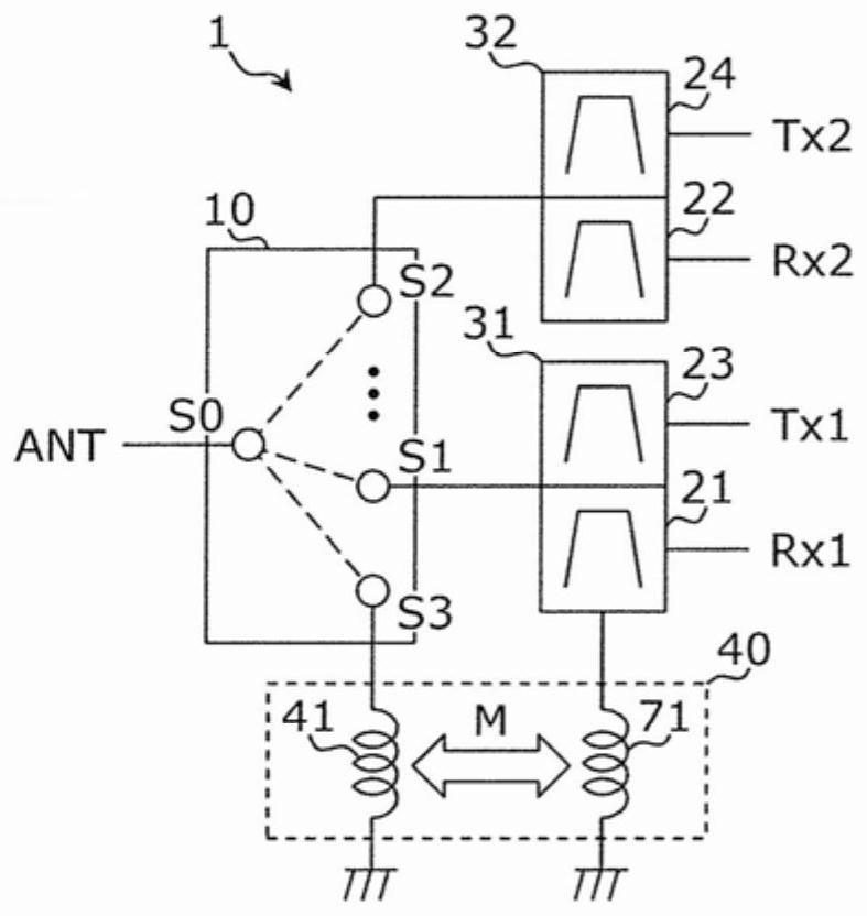
[0026] figure 1 It is a circuit diagram showing an example of the configuration of the multiplexer of the embodiment. Such as figure 1 As shown, the multiplexer 1 includes a switch 10 , filters 21 , 22 , 23 , and 24 , and inductors 41 , 71 . The filters 21 and 23 constitute a duplexer 31 , and the filters 22 and 24 constitute a duplexer 32 . The inductors 41 and 71 constitute the coupling circuit 40 .

[0027] The switch 10 has a common terminal S0 and selection terminals S1 , S2 , and S3 , and can simultaneously connect the common terminal S0 to one or more selection terminals among the selection terminals S1 , S2 , and S3 . It is also possible that the switch 10 ...


PUM


Abstract

A multiplexer (2) is provided with: a switch (10) capable of simultaneously connecting a common terminal (S0) and one or more selection terminals among a first selection terminal (S1), a second selection terminal (S2), and a third selection terminal (S3); a first filter (21) connected to the first selection terminal (S1) and having a first passband; a second filter (22) connected to the second selection terminal (S2) and having a second passband different from the first passband; and a coupling circuit (40) connected to the third selection terminal (S3) and the first filter (21), and forming asignal path by electromagnetic field coupling (M) between the third selection terminal (S3) and the first filter (21).

Description

technical field [0001] The present invention relates to a multiplexer, in particular to a multiplexer applied to carrier aggregation. Background technique [0002] There are communication devices corresponding to multiple frequency bands (multi-band) and multiple wireless systems (multi-mode). The front-end circuit of such a communication device uses a multiplexer for demultiplexing and multiplexing signals of a plurality of frequency bands. The multiplexer is composed of, for example, a plurality of filter circuits having different passbands. [0003] A technique called carrier aggregation (hereinafter, abbreviated as CA) for performing communications using two or more frequency bands constituting a multi-band is also being put into practical use. In a multiplexer applied to CA, two or more filter circuits are used simultaneously to process two or more signals with different frequency bands. [0004] Patent Document 1 discloses a filter circuit including a filter unit ha...

Claims


Application Information

Patent Timeline
Patent Type & Authority Applications(China)
IPC IPC(8): H04B1/401H03H7/46H04B1/00
CPCH04B1/00H04B1/401H03H9/706H03H9/725H03H9/542H03H7/09H03H9/605H03H9/70H04J1/02
Inventor 花冈邦俊
Owner MURATA MFG CO LTD
Why Eureka
Try Eureka