A kind of additive manufacturing method and its preparation method and device using powder core wire

A technology of additive manufacturing and powder core wire, applied in the field of additive manufacturing, can solve problems such as difficult to achieve continuous and precise changes in composition, single alloy composition, etc., to achieve the effects of improving composition editing accuracy, avoiding process restrictions, and retaining flexibility

Active Publication Date: 2021-09-24
NORTHWESTERN POLYTECHNICAL UNIV
View PDF8 Cites 0 Cited by
  • Summary
  • Abstract
  • Description
  • Claims
  • Application Information

AI Technical Summary

Problems solved by technology

[0006] The purpose of the present invention is to overcome the above-mentioned shortcomings of the prior art. The purpose of the present invention is to provide an additive manufacturing method and its preparation method and device using powder core wire, and realize the alloying of metal parts through the change of powder core wire composition. The precise point-to-point control of the composition solves the problems in the prior art that the alloy composition is single or it is difficult to achieve continuous and precise change of composition

Method used


Image

  • A kind of additive manufacturing method and its preparation method and device using powder core wire
  • A kind of additive manufacturing method and its preparation method and device using powder core wire
  • A kind of additive manufacturing method and its preparation method and device using powder core wire

Examples


Embodiment 1

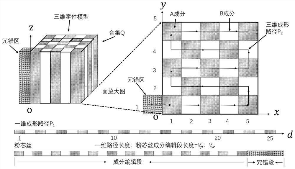
[0085] Such as Figure 1-Figure 3 shown. according to figure 1 , for a given component set Q={x, y, z, C}, it is composed of components A and B intervals, where the functional relationship between components and positions is:

[0086]

[0087] according to figure 1 Planning 3D Forming Paths

[0088] P 3

[0089] ={(1,1,0,C A )...(5,1,0,C A ),(5,2,0,C B )...(1,2,0,C B ),(1,3,0,C A )...(5,3,0,C A ),(5,4,0,C B )...(1,4,0,C B )(1,5,0,C A )...(5,5,0,C A );(1,1,1,C A )...(5,1,1,C A ),(5,2,1,C B )...(1,2,1,C B ),(1,3,1,C A )...(5,3,1,C A ),(5,4,1,C B )...(1,4,1,C B )(1,5,1,C A )...(5,5,1,C A );...}.

[0090] Through the coordinate transformation law, the three-dimensional forming path P in this example can be 3 ={x,y,C} is transformed into a one-dimensional shaping path P 1 =

[0091] {d,C}, where so

[0092] P 1 ={(1,C A ),(2,C B ),(3,C A )…(25,C A );(26,C A )…} (13)

[0093]Similarly, according to this rule, the alloy composition function C(...

Embodiment 2

[0104] In a typical implementation of this application, such as Figure 2-Figure 4 shown. according to Figure 4 , for a given part composition set Q={ρ,θ,z,C}, which is composed of components A and B intervals, where the components And, the forming speed is

[0105] Further, plan the 3D forming path And according to the coordinate transformation law, the three-dimensional forming path P 3 {ρ,θ,C} into a one-dimensional shaped path

[0106] Similarly, according to this rule, the three-dimensional alloy composition function can be transformed into a one-dimensional alloy composition function Set the wire feed speed to Where l is the length of the powder core wire. Among them, the one-dimensional forming path distance d and the powder core wire length l satisfy the relationship: (in this example set ). Therefore, combining the above formulas, we can get

[0107] And, add a redundant segment with a length of a (in this example, a=2.3) and a ...


PUM


Abstract

The invention also discloses an additive manufacturing method and a preparation method and device using the powder core wire. The powder core wire is composed of two parts, the metal sheath and the core powder, in which the core powder is made by mixing powders of different components in any proportion, so that the final chemical composition can be changed arbitrarily. This not only retains the flexibility of changing the chemical composition of the mixed powder method, but also avoids the uncontrollable influencing factors in the powder conveying process in the multi-channel powder feeding technology and the process limitation of the multi-channel wire feeding technology. As a result, metal additive manufacturing technology with arbitrary changes in composition is realized; using the powder core wire for additive manufacturing can realize multi-component 3D printing of the three-dimensional geometric structure of the part and the alloy composition.

Description

【Technical field】 [0001] The invention belongs to the technical field of additive manufacturing, and in particular relates to an additive manufacturing method and a preparation method and device using powder core wire. 【Background technique】 [0002] Additive manufacturing technology uses lasers, electric arcs, plasma arcs, and electron beams as heat sources to melt and deposit metal powders / core wires layer by layer to form high-performance metal parts with the required geometric structure. Arbitrary, short cycle and other manufacturing features. At the same time, this technology is also a low energy consumption, sustainable green manufacturing technology. In particular, since additive manufacturing technology is not limited by the geometric structure of parts, it has greatly promoted innovative design and empowered the development of various industries. [0003] At present, under the advantage of manufacturing any three-dimensional structure (3D), adding the dimension of...

Claims


Application Information

Patent Timeline
Patent Type & Authority Patents(China)
IPC IPC(8): B22F10/18B22F12/00B22F10/85B22F12/50B33Y50/02B33Y70/00B33Y10/00B33Y30/00B33Y40/00
CPCB22F3/003B33Y10/00B33Y30/00B33Y40/00Y02P10/25
Inventor 王理林丁汉林林鑫黄卫东
Owner NORTHWESTERN POLYTECHNICAL UNIV
Why Eureka
Try Eureka