
Tool for adjusting perpendicularity and coaxiality of workbench

A workbench and verticality technology, applied in the field of tooling and fixtures, can solve the problems of large verticality error, low production efficiency, large coaxiality deviation of double-row bearing holes, etc.

Pending Publication Date: 2020-12-22
HANS LASER TECH IND GRP CO LTD
View PDF0 Cites 0 Cited by
  • Summary
  • Abstract
  • Description
  • Claims
  • Application Information

AI Technical Summary

Problems solved by technology

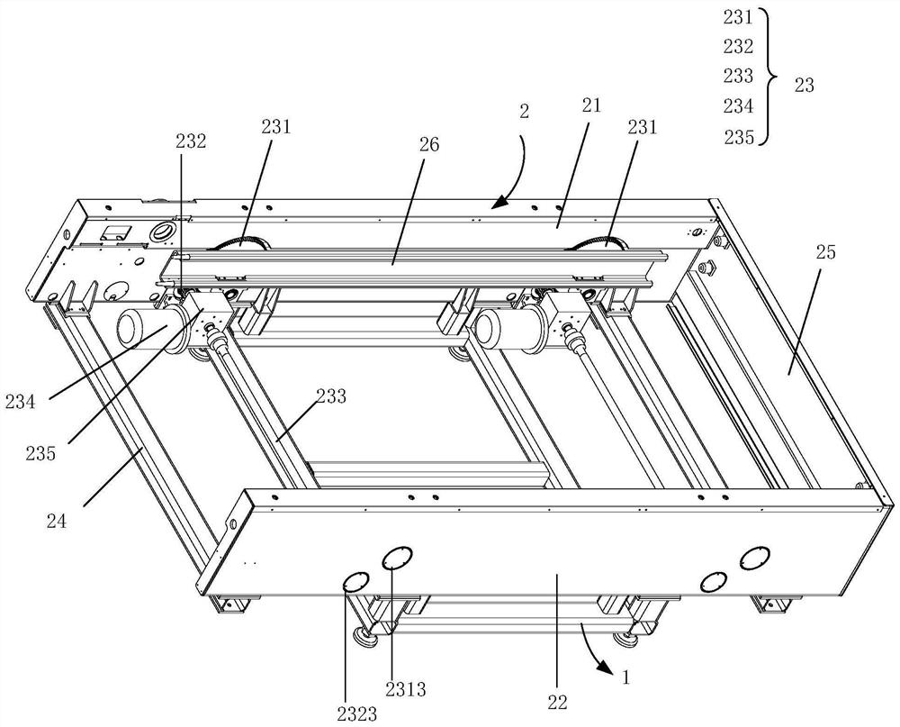
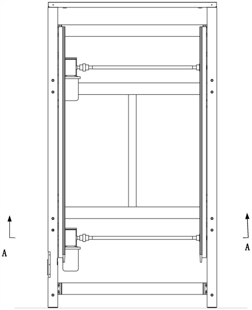
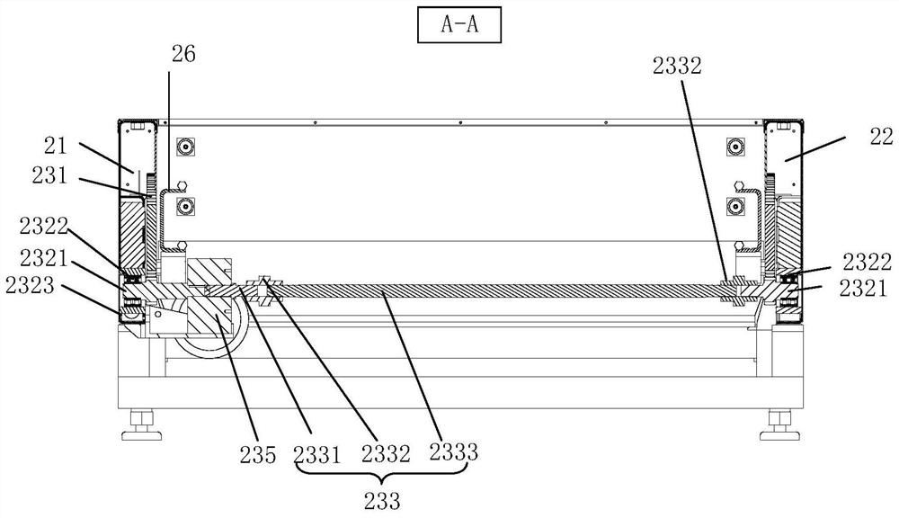
[0002] The gear lifting type transmission exchange table is composed of the first side plate, the second side plate, the fixed plate, and the connecting bracket. The first side plate and the second side plate are connected and fixed by the connecting bracket. When installing, use a right angle Use the ruler to detect that the angle between the finishing surface of the first side plate and the connecting bracket is vertical, and the angle between the finishing surface of the second side plate and the connecting bracket is vertical, then connect the fixing plate to the first side plate, The second side plate is connected and fixed, because there is no high-precision positioning fixture to assist in the installation, after the first side plate and the second side plate are installed, the verticality error between the first side plate, the second side plate and the horizontal direction is prone to occur Larger, and the coaxiality of the double-row bearing holes installed on the first side plate and the second side plate also has a large deviation. There is also a transmission long shaft installed between the first side plate and the second side plate. After the shaft is installed, when the small gear shaft of the exchange table drives the big gear to move up and down, relatively large vibration and noise will be generated. This method of assembly not only reduces the bearing load, but also the coupling bolts are easy to overload and break, and the production efficiency is low.

Method used


Image

  • Tool for adjusting perpendicularity and coaxiality of workbench
  • Tool for adjusting perpendicularity and coaxiality of workbench
  • Tool for adjusting perpendicularity and coaxiality of workbench

Examples


Embodiment Construction

[0040] Unless otherwise defined, all technical and scientific terms used herein have the same meaning as commonly understood by one of ordinary skill in the technical field of the invention. The terms used herein in the description of the present invention are for the purpose of describing specific embodiments only, and are not intended to limit the present invention. The terms "comprising" and "having" and any variations thereof in the specification and claims of the present invention and the above descriptions of the drawings are intended to cover non-exclusive inclusion. The terms "first", "second" and the like in the description and claims of the present invention or the above drawings are used to distinguish different objects, rather than to describe a specific order.

[0041] Reference herein to an "embodiment" means that a particular feature, structure, or characteristic described in connection with the embodiment can be included in at least one embodiment of the presen...


PUM


Abstract

The invention discloses a method and tool for adjusting the perpendicularity and coaxiality of a workbench. The tool involves the workbench and a supporting frame, the workbench is located on the upper portion of the supporting frame and comprises side plates, vertical positioning assemblies and horizontal positioning assemblies are arranged on the supporting frame, wherein each vertical positioning assembly comprises a reference vertical face arranged in the vertical direction, the vertical side faces of the side plates are tightly attached to the reference vertical faces so as to adjust theverticality of the side plates, each horizontal positioning assembly comprises a reference horizontal face arranged in the horizontal direction, a protruding step is further arranged on each referencehorizontal face, bosses are arranged at the positions, corresponding to the reference horizontal faces, of the bottom faces of the side plates, boss faces of the bosses are tightly attached to the reference horizontal face so as to adjust the levelness of the bottom faces of the side plates. and the bosses and the steps are clamped so as to realize the positioning of the side plates in the horizontal direction. Compared with the prior art, the perpendicularity of the two side plates of the workbench can be quickly positioned, and the positions of the two side plates in the horizontal direction are quickly positioned, so that the coaxiality reaches the standard.

Description

technical field [0001] The invention relates to the technical field of fixtures, in particular to a fixture for adjusting the verticality and coaxiality of a workbench. Background technique [0002] The gear lifting type transmission exchange table is composed of the first side plate, the second side plate, the fixed plate, and the connecting bracket. The first side plate and the second side plate are connected and fixed by the connecting bracket. When installing, use a right angle Use the ruler to detect that the angle between the finishing surface of the first side plate and the connecting bracket is vertical, and the angle between the finishing surface of the second side plate and the connecting bracket is vertical, then connect the fixing plate to the first side plate, The second side plate is connected and fixed, because there is no high-precision positioning fixture to assist in the installation, after the first side plate and the second side plate are installed, the v...

Claims


Application Information

Patent Timeline
Patent Type & Authority Applications(China)
IPC IPC(8): B25H1/00B25H1/14
CPCB25H1/00B25H1/14
Inventor 严奋婵陈焱杜彪邬建鸿彭海锋钟振亮高云峰
Owner HANS LASER TECH IND GRP CO LTD
Learn More