
Strip material cutting mechanism

A cutting and passing technology, which is applied in the direction of strapping materials, strapping machine parts, paper/cardboard containers, etc., can solve the problem that the cable tie is easy to break, the head end and the end of the cable tie cannot be completely overlapped, and the cable tie Offset and other issues

Pending Publication Date: 2020-12-22
佛山市爱立德机械有限公司
View PDF0 Cites 0 Cited by
  • Summary
  • Abstract
  • Description
  • Claims
  • Application Information

AI Technical Summary

Problems solved by technology

However, when the cable tie enters from the feeding end of the material cutting mechanism and passes over the heating structure, the cable tie may also be offset, which will also cause the head end and the end of the cable tie bundled on the product to not completely overlap Together, the heating assembly cannot completely thermally bond the head and end of the cable tie together, and the cable tie is easily disconnected after the material mechanism cuts the cable tie

Method used


Image

  • Strip material cutting mechanism
  • Strip material cutting mechanism
  • Strip material cutting mechanism

Examples


Embodiment Construction

[0020] A number of embodiments of the present invention will be disclosed in the following figures. For the sake of clarity, many practical details will be described together in the following description. It should be understood, however, that these practical details should not be used to limit the invention. That is, in some embodiments of the invention, these practical details are not necessary. In addition, for the sake of simplifying the drawings, some well-known and commonly used structures and components will be shown in a simple schematic manner in the drawings.

[0021] It should be noted that all directional indications (such as up, down, left and right, front, back...) in the embodiments of the present invention are only used to explain the relative positions of the components in a certain posture (as shown in the drawings) relationship, motion, etc., if the particular pose changes, the directional indication changes accordingly.

[0022] In addition, in the presen...


PUM


Abstract

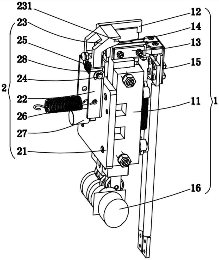
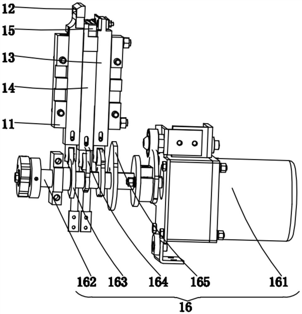
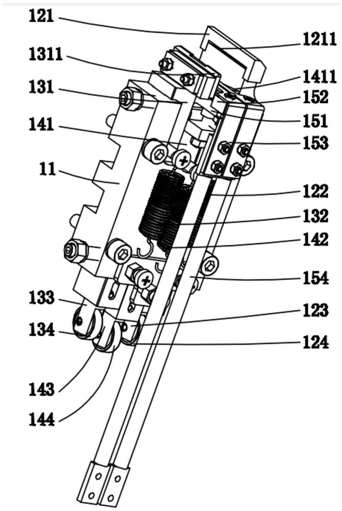
The invention discloses a strip material cutting mechanism. The strip material cutting mechanism comprises a material cutting component and a material cutting guide component, wherein the material cutting component comprises a cutter rest, a material cutting and passing group, a material cutting group, a material cutting and pressing group, a material cutting and heating group and a lifting driving group; the material cutting and passing group, the material cutting group and the material cutting and pressing group are slidably connected to the cutter rest; the material cutting and passing group is used for enabling a strip material output by a feeding and conveying component to pass; the material cutting group is used for cutting the strip material; the material cutting and pressing groupis used for pressing the other end of the strip material when the strip material is cut; the material cutting and heating group is arranged on the material cutting and pressing group and is used for heating the strip material; and the material cutting guide component is used for guiding the strip material when the strip material enters the material cutting component from the feeding and conveyingcomponent. Compared with the prior art, the strip material cutting mechanism has the advantages that a strip guide groove guides the strip material and guides the strip material to penetrate through when the strip material enters the material cutting component from the feeding and conveying component, partial strip blocking of the strip material on the material cutting component is reduced, meanwhile, deviation of a binding strip during conveying at the material cutting mechanism is avoided, and the binding quality is improved.

Description

technical field [0001] The invention relates to the technical field of automatic strapping machines, in particular to a tape cutting mechanism. Background technique [0002] Automatic strapping machine is currently widely used packaging equipment, which uses film to achieve strapping and packaging of products through steps such as tensioning, tape cutting, and strapping. In the automatic strapping process, the product needs to be fed into the strapping cavity, and the product is bundled by the film feeding device and the tightening device. After the bundling is completed, the film is cut with a cutter, and the two ends of the film are fused together by heating. However, when the cable tie enters from the feed end of the material cutting mechanism and passes over the heating structure, the cable tie may also be offset, which will also cause the head end and end of the cable tie bundled on the product to not completely overlap Together, the heating assembly cannot completely...

Claims


Application Information

Patent Timeline
Patent Type & Authority Applications(China)
IPC IPC(8): B65B61/10B65B13/04B65B13/18B65B61/00
CPCB65B13/04B65B13/18B65B13/183B65B61/00B65B61/10
Inventor 刘燊
Owner 佛山市爱立德机械有限公司
Learn More