Induction heating furnace with induction coil clearance type heat dissipation

A technology of induction heating furnace and induction coil, which is applied in the direction of induction heating, electric furnace heating, coil device, etc., which can solve the problems that the induction coil generates too much heat and natural heat dissipation cannot meet the requirements of use, and achieve the effect of long-term work

Active Publication Date: 2020-12-22
安徽宏达电炉科技有限公司
View PDF6 Cites 1 Cited by
  • Summary
  • Abstract
  • Description
  • Claims
  • Application Information

AI Technical Summary

Problems solved by technology

[0003] Most of the induction coils of existing induction heating furnaces use natural heat dissipation, but when working for a long time, the induction coils generate more heat, and natural heat dissipation cannot meet the requirements of use

Method used


Image

  • Induction heating furnace with induction coil clearance type heat dissipation
  • Induction heating furnace with induction coil clearance type heat dissipation
  • Induction heating furnace with induction coil clearance type heat dissipation

Examples


Embodiment 1

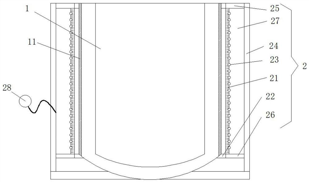
[0020] like figure 1 As shown, the induction heating furnace for the induction coil gap heat dissipation described in this embodiment includes a furnace 1, and the outside of the furnace 1 is provided with a coil installation mechanism 2, and the coil installation mechanism 2 includes an inner cylinder 21. The inner cylinder 21 is coaxially sleeved on the furnace 1, and the inner wall of the inner cylinder 21 is fixedly connected with several connecting blocks 22, and the connecting blocks 22 are also fixedly connected to the outer wall of the furnace 1, and the two ends of the inner cylinder 21 are Open, and there are a plurality of through holes evenly on the wall of the inner cylinder 21, the outer wall of the inner cylinder 21 is wound with an induction coil 23, and the adjacent coils on the induction coil 23 do not contact each other. The outer coaxial sleeve of the inner cylinder 21 is provided with an outer cylinder 24, and the top and bottom ends between the outer cyli...

Embodiment 2

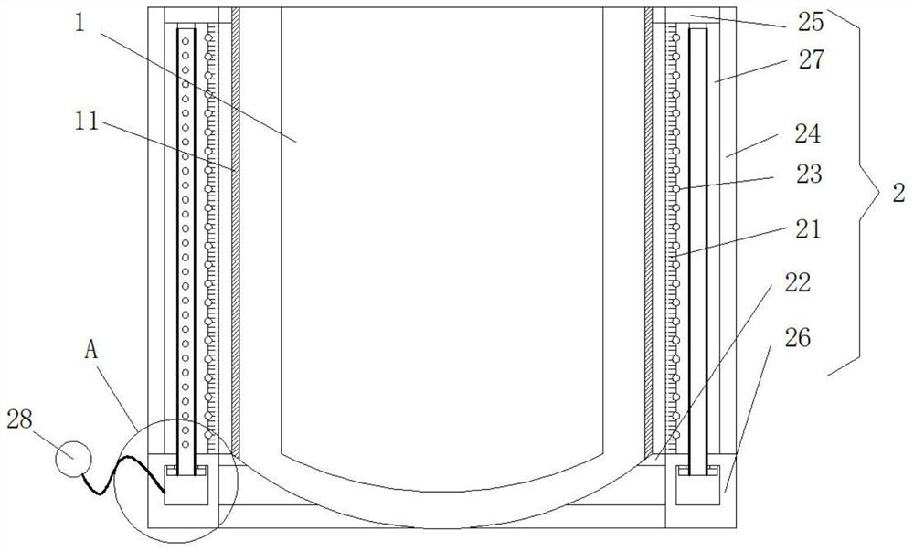
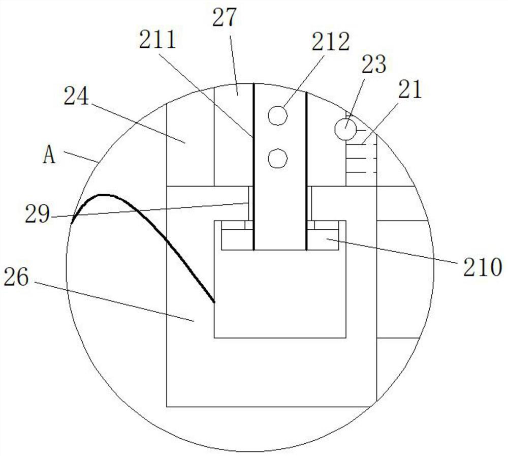
[0026] like Figure 2-3 As shown, the induction heating furnace for the induction coil gap heat dissipation described in this embodiment includes a furnace 1, and the outside of the furnace 1 is provided with a coil installation mechanism 2, and the coil installation mechanism 2 includes an inner cylinder 21. The inner cylinder 21 is coaxially sleeved on the furnace 1, and the inner wall of the inner cylinder 21 is fixedly connected with several connecting blocks 22, and the connecting blocks 22 are also fixedly connected to the outer wall of the furnace 1, and the two ends of the inner cylinder 21 are Open, and there are a plurality of through holes evenly on the wall of the inner cylinder 21, the outer wall of the inner cylinder 21 is wound with an induction coil 23, and the adjacent coils on the induction coil 23 do not contact each other. The outer coaxial sleeve of the inner cylinder 21 is provided with an outer cylinder 24, and the top and bottom ends between the outer c...


PUM


Abstract

The invention provides an induction heating furnace with induction coil clearance type heat dissipation. The induction heating furnace with induction coil clearance type heat dissipation is characterized in that a coil mounting mechanism is arranged outside a furnace pipe, and comprises an inner cylinder; the furnace pipe is coaxially sleeved with the inner cylinder; a plurality of connecting blocks are fixedly connected to the inner wall of the inner cylinder, and are further fixedly connected with the outer wall of the furnace pipe; two ends of the inner side of the inner cylinder are open;and a plurality of through holes are uniformly formed in the cylinder wall of the inner cylinder. An induction coil is wound on the outer wall of the inner cylinder; adjacent coils on the induction coil are not in contact; the inner cylinder is externally coaxially sleeved with an outer cylinder; a first sealing ring and a second sealing ring are arranged at the top end and the bottom end betweenthe outer cylinder and the inner cylinder respectively, and seal the top end and the bottom end of the part between the outer cylinder and the inner cylinder respectively; a cavity is formed between the outer cylinder and the inner cylinder, and communicates with an air pump through a pipeline; and the air pump pumps air into the cavity. According to the technical scheme, active heat dissipation is adopted for the induction coil, so that the requirement for long-time work can be met.

Description

technical field [0001] The invention relates to the technical field of induction heating furnaces, in particular to an induction heating furnace for gap heat dissipation of induction coils. Background technique [0002] The induction heating furnace is a power supply device that converts the power frequency 50HZ AC power into an intermediate frequency (300HZ to 1000HZ). The medium-frequency alternating current flowing through the capacitor and the induction coil generates high-density magnetic force lines in the induction coil, and cuts the metal material contained in the induction coil, generating a large eddy current in the metal material. Put the workpiece into the inductor (coil), and when an alternating current of a certain frequency is passed into the inductor, an alternating magnetic field is generated around it. The electromagnetic induction of the alternating magnetic field causes a closed induced current in the workpiece—eddy current. The distribution of induced ...

Claims


Application Information

Patent Timeline
Patent Type & Authority Applications(China)
IPC IPC(8): F27B14/06F27B14/14F27D11/06F27B14/08F27D1/00H05B6/42
CPCF27B14/061F27B14/14F27D11/06F27B14/08F27D1/0033H05B6/42F27B2014/0843
Inventor 汪绍松
Owner 安徽宏达电炉科技有限公司
Why Eureka
Try Eureka