A high frequency intermittent valve device based on valve core rotation

A valve core rotating, intermittent valve technology, applied in the valve operation/release device, valve device, cock including cut-off device, etc. The effect of a wide range, wide range, high intermittent operating frequency

Active Publication Date: 2022-07-08
CHANGZHOU INST OF TECH
View PDF7 Cites 0 Cited by
  • Summary
  • Abstract
  • Description
  • Claims
  • Application Information

AI Technical Summary

Problems solved by technology

[0004] The purpose of the present invention is to provide a high-frequency intermittent valve device based on the rotation of the spool, which solves the technical problem of the contradiction between the low operating frequency of the traditional solenoid valve and the gradually increasing frequency of use in the prior art

Method used


Image

  • A high frequency intermittent valve device based on valve core rotation
  • A high frequency intermittent valve device based on valve core rotation
  • A high frequency intermittent valve device based on valve core rotation

Examples


Embodiment 1

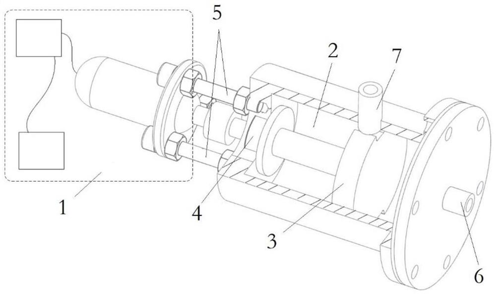
[0059] like Figure 1-7 As shown, a high-frequency intermittent valve device based on valve core rotation provided in this embodiment includes:

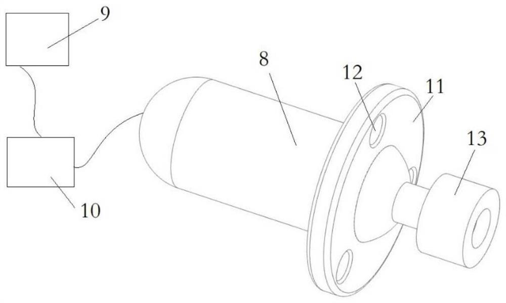
[0060] Drive assembly 1, the drive assembly 1 is composed of a servo motor 8, a controller 9 and a driver 10, and the speed of the servo motor 8 is controlled by the controller 9 during use, thereby further controlling the speed of the rotary valve core 3;

[0061] Fluid chamber 2, the fluid chamber 2 is a cylindrical component;

[0062] The rotary valve core 3 is installed inside the fluid chamber 2, and the end of the rotary valve core 3 is connected to the drive assembly 1. In this embodiment of the present application, the drive assembly drives the rotary valve core 3 to move in the fluid. Cavity 2 rotates inside;

[0063] a fluid outlet 7, the fluid outlet 7 is arranged on the side of the fluid chamber 2;

[0064] A fluid inlet 6 is provided at the end of the fluid chamber 2 .

[0065] Specifically, the drive assembly 1 incl...


PUM


Abstract

The invention discloses a high-frequency intermittent valve device based on valve core rotation, comprising: a driving component; a fluid chamber; The outlet, the fluid outlet is arranged on the side of the fluid chamber; the fluid inlet, the fluid inlet is arranged at the end of the fluid chamber. The invention solves the technical problem of the existing contradiction between the low operating frequency of the traditional solenoid valve and the gradually increasing use frequency in the prior art.

Description

technical field [0001] The present invention relates to the technical field of fluid delivery control, in particular to a high-frequency intermittent valve device based on valve core rotation. Background technique [0002] In the fields of aerospace, automobiles, ships, etc., various forms of control valves are widely used in fluid transportation systems, such as controlling fluid on-off, adjusting flow size, and adjusting flow direction. The choice of valve form is mainly based on the functional requirements to be achieved. In some cases, it is necessary to realize intermittent flow path opening and closing through valve control, that is, pulsed fluid transport. For example, in a piston-type internal combustion engine, oil supply is only required for the intake stroke, while the oil supply system for other strokes is closed; for example, in the combustion equipment, due to the mutual coupling between the fuel combustion heat release pulsation and the pressure pulsation, th...

Claims


Application Information

Patent Timeline
Patent Type & Authority Patents(China)
IPC IPC(8): F16K5/04F16K5/08F16K5/22F16K27/06F16K31/04
CPCF16K5/0407F16K5/0442F16K5/0485F16K5/08F16K5/225F16K27/065F16K31/042Y02T10/12
Inventor 巩二磊孙志军张琪萱张明辰李进李思玉
Owner CHANGZHOU INST OF TECH
Why Eureka
Try Eureka