
Multi-density interface inversion method for complex geologic body

A technology of density inversion and complex land, applied in the field of geophysics, can solve problems such as inversion calculation result deviation, achieve the effect of improving inversion accuracy, solving poor convergence, and improving accuracy

Active Publication Date: 2020-12-22
天津市地球物理勘探中心
View PDF6 Cites 2 Cited by
  • Summary
  • Abstract
  • Description
  • Claims
  • Application Information

AI Technical Summary

Problems solved by technology

[0005] The purpose of the present invention is to provide a multi-density interface inversion method for complex geological bodies that solves the problem that the inversion calculation results of the multi-density layer interface of complex geological bodies obtained based on the Parker-Oldenburg inversion method have relatively large deviations

Method used


Image

  • Multi-density interface inversion method for complex geologic body
  • Multi-density interface inversion method for complex geologic body
  • Multi-density interface inversion method for complex geologic body

Examples


Embodiment 1

[0091] Firstly, the multi-density interface inversion method of this complex geological body is simulated through the simulation model, and the specific operation steps are as follows:

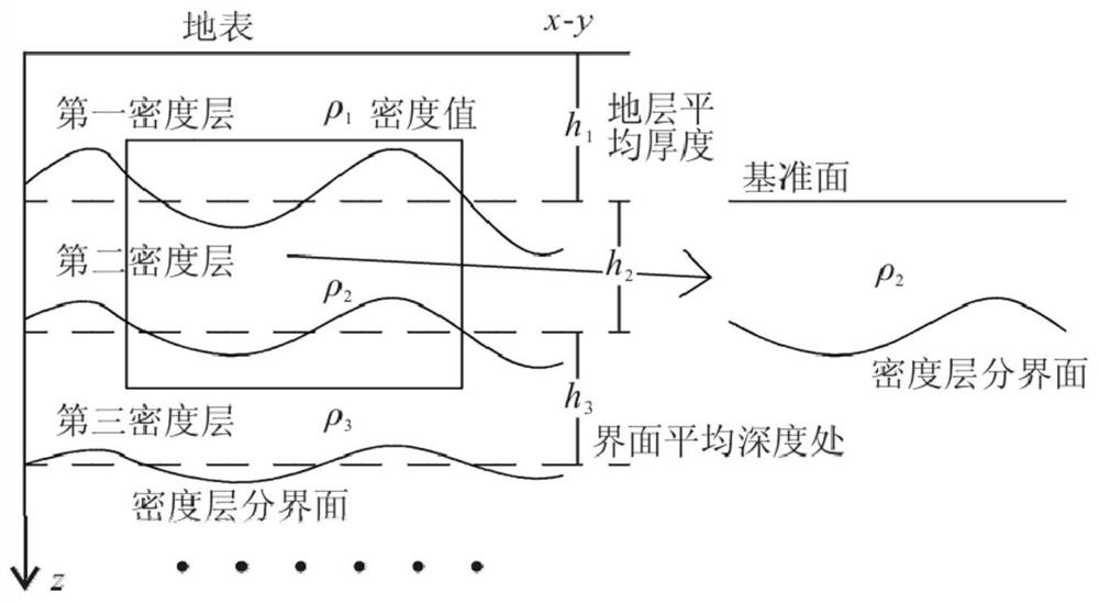
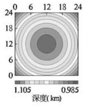
[0092] S1, such as figure 1 As shown, a theoretical model of a complex geological body is constructed: the length and width of the model are both 24km, including four density layers and three stratigraphic boundaries;

[0093] Build a density inversion model consistent with the target complex geological body: take the surface as the x-y plane, and the depth direction as the z-axis direction, and construct the first density layer, the second density layer, the third density layer and the The fourth density layer; the density corresponding to each density layer from top to bottom is: 1.95g / cm 3 , 2.15g / cm 3 , 2.40g / cm 3 and 2.70g / cm 3 ; The interface between each density layer and its lower density layer is the bottom interface of the density layer, which corresponds to: the bottom interface...

Embodiment 2

[0107] The specific implementation method of the multi-density interface inversion method of the present invention is further explained below by taking the Tuanbo-Dasi area of ​​Tianjin as an example. The steps are as follows:

[0108] S1. Construct a density inversion model consistent with the target complex geological body:

[0109] According to the data of density and physical properties in the study area, the gravity field of the Tuanbo-Dasi area in Tianjin is located in the high-value area of ​​gravity in the central part of Tianjin, and the Bouguer gravity anomaly in the area mainly includes a high trap anomaly and a low trap anomaly. NE-SW is distributed in an elliptical shape, and the structure is located on the Cangxian uplift of the third-level structural unit. The area is divided into four fourth-level structural units, namely Dacheng uplift, Shuangyao uplift, Baitangkou sag and Xiaohanzhuang uplift It is sandwiched between the Cangdong fault and the Tianjin fault, ...


PUM


Abstract

The invention discloses a multi-density interface inversion method of a complex geologic body. The method comprises the following steps: constructing a density inversion model conforming to a target complex geologic body; substituting the actually measured Bouge gravity anomaly g at the earth surface into a cutting method calculation formula based on a potential field separation purpose so as to solve gravity anomalies generated by the bottom interface of each density layer on the ground; extending gravity anomalies generated by the bottom interface of each density layer of the target complexgeologic body on the ground to a reference surface by applying a potential field large-depth downward extension method; and sequentially performing interface inversion on the gravity anomaly caused bythe bottom interface of each density layer on the reference surface to obtain the depth of each interface relative to the reference surface, thereby obtaining the actual depth of the bottom interfaceof each density layer. According to the inversion method, the actual distribution condition of the density layer of the complex geologic body can be effectively obtained, the accuracy of an inversionresult is improved, and compared with a Parker-Oldenburg inversion method, the inversion precision can be improved by 1%-6%.

Description

technical field [0001] The invention relates to the technical field of geophysics, in particular to a multi-density interface inversion method for complex geological bodies. Background technique [0002] The Parker-Oldenburg inversion method is an iterative inversion method for the density interface in the frequency domain proposed by Oldenburg based on the Parker formula. Due to the advantages of fast calculation of this method, its application has been developed rapidly. However, there is a downward continuation factor in the formula, which makes the formula have a phenomenon of high-frequency signal oscillation during the inversion iteration process, and as the inversion depth increases, this phenomenon becomes more obvious, which seriously affects the inversion results. Convergence. In order to solve this situation, a low-pass filter is usually used in the inversion process to eliminate high-frequency oscillations. In this way, although the inversion results can be gua...

Claims


Application Information

Patent Timeline
Patent Type & Authority Applications(China)
IPC IPC(8): G01V7/00
CPCG01V7/00
Inventor 郑国磊徐新学李爱国曹朋军雷清李世斌袁航范剑吴晓飞
Owner 天津市地球物理勘探中心
Learn More