
Low-voltage cabinet with visual temperature rise state

A low-voltage cabinet and status technology, applied in the field of low-voltage cabinets, can solve problems such as potential safety hazards, excessive temperature rise, and performance degradation of components to achieve the effect of ensuring structural strength

Pending Publication Date: 2020-12-22
镇江茗驰电气有限公司
View PDF0 Cites 0 Cited by
  • Summary
  • Abstract
  • Description
  • Claims
  • Application Information

AI Technical Summary

Problems solved by technology

[0002] During the operation of ordinary low-voltage cabinets, the overlapping joints of horizontal busbars and pile head copper bars are prone to excessive or even super high temperature rise.
Especially in the high-current circuit, the high temperature of the conductor copper bar will cause local derating, and the low-voltage cabinet under high temperature for a long time will have great safety hazards, resulting in accelerated aging of insulating parts and performance degradation of components.
In the existing technology, inspectors can only know the temperature rise in the low-voltage cabinet by opening the cabinet door and measuring it with a temperature gun. They cannot quickly know the situation inside the cabinet from the outside, making it easy for inspectors to ignore the temperature rise problem and cause potential safety hazards.

Method used


Image

  • Low-voltage cabinet with visual temperature rise state
  • Low-voltage cabinet with visual temperature rise state
  • Low-voltage cabinet with visual temperature rise state

Examples


Embodiment Construction

[0017] In order to deepen the understanding of the present invention, the present invention will be further described below in conjunction with the embodiments and accompanying drawings. The embodiments are only used to explain the present invention and do not constitute a limitation to the protection scope of the present invention.

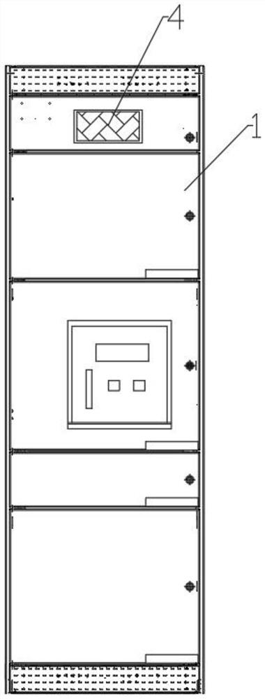
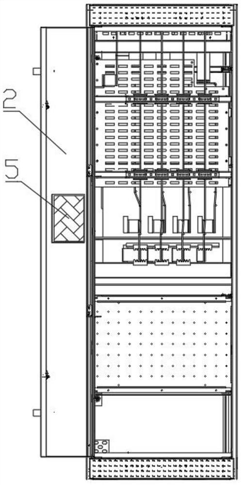
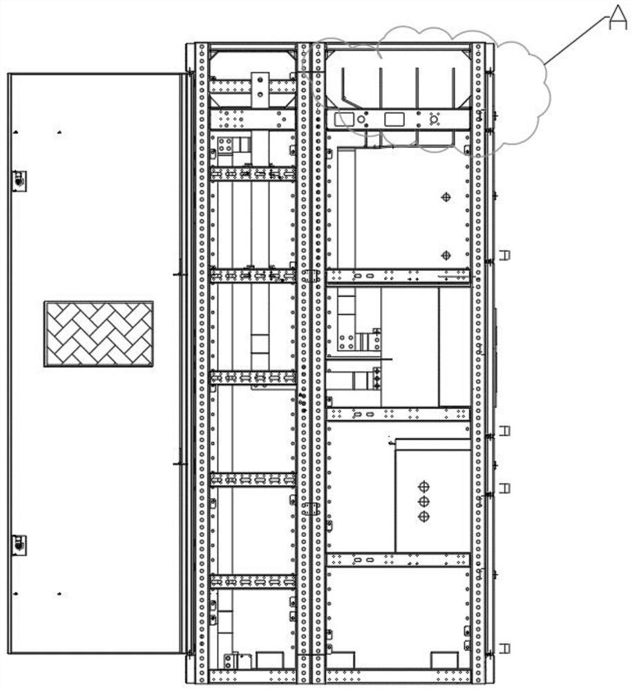
[0018] Such as Figure 1-6 As shown, a low-voltage cabinet that can visually observe the temperature rise state includes a cabinet body, a front cabinet door 1, a rear cabinet door 2, and a conductor copper bar 3. The front cabinet door 1 is located at the uppermost busbar room and has a main The sight hole 4 of the busbar, the middle part of the rear cabinet door 2 is provided with the sight hole 5 of the copper bar behind the cabinet, the sight hole of the copper bar behind the cabinet is located at the overlap between the vertical copper bar and the horizontal copper bar of the low-voltage cabinet, the said High-strength tempered glass is inst...


PUM

PropertyMeasurementUnit
thermal resistanceaaaaaaaaaa

Abstract

The invention discloses a low-voltage cabinet with a visual temperature rise state, and the cabinet comprises a cabinet body, a front cabinet door, a rear cabinet door and a conductor copper bar; a main bus visual hole is formed in the front cabinet door at the uppermost bus chamber, and a cabinet rear copper bar visual hole is formed in the middle of the rear cabinet door; the cabinet rear copperbar visual holes and the main bus visual holes are provided with high-strength toughened glass. The conductor copper bars are sleeved with thermosensitive color-changing sleeves, and the thermosensitive color-changing sleeves are located at the positions close to the lap joint ends of the conductor copper bars. According to the invention, the specific part of the conductor copper bar is sleeved with the thermosensitive color-changing sleeve, and the observation hole is formed in the corresponding position of the cabinet door, so an inspector can obtain the temperature rise state in the cabinet through visual observation outside the cabinet, and meanwhile, the high-strength toughened glass not only meets the observation requirement, but also ensures the structural strength of the cabinet body.

Description

technical field [0001] The invention relates to the technical field of low-voltage power distribution design, and in particular relates to a low-voltage cabinet whose temperature rise state can be visually observed. Background technique [0002] During the operation of ordinary low-voltage cabinets, the overlapping joints of horizontal bus bars and pile head copper bars are prone to excessive or even super high temperature rise. Especially in the high-current circuit, the high temperature of the conductor copper bar will cause local derating, and the low-voltage cabinet under high temperature for a long time will have great safety hazards, resulting in accelerated aging of insulating parts and performance degradation of components. In the existing technology, inspectors can only know the temperature rise in the low-voltage cabinet by opening the cabinet door and measuring it with a temperature gun. They cannot quickly know the situation inside the cabinet from the outside, m...

Claims


Application Information

Patent Timeline
Patent Type & Authority Applications(China)
IPC IPC(8): H02B1/30G01K11/12
CPCG01K11/12H02B1/30
Inventor 朱进贤谢汝荣
Owner 镇江茗驰电气有限公司
Learn More