AI technical title is built by Patsnap AI team. It summarizes the technical point description of the patent document.
A mixer, automatic technology, applied in mixers, mixer accessories, mixers with rotating mixing devices, etc., can solve problems such as inconvenience, achieve the effect of convenient use of equipment and speed up material mixing
Inactive Publication Date: 2020-12-25
黄彬
View PDF5 Cites 1 Cited by
Summary
Abstract
Description
Claims
Application Information
AI Technical Summary
This helps you quickly interpret patents by identifying the three key elements:
Problems solved by technology
Method used
Benefits of technology
Problems solved by technology
[0003] At present, when mixing materials, they are mixed by stirring. First, put different types of materials into the container, and then mix by stirring. During the mixing process, it is necessary to continuously add materials. very inconvenient
Method used
Image
Click on the blue label to locate the original text in one second.
Reading with bidirectional positioning of images and text.
Examples
Embodiment 1
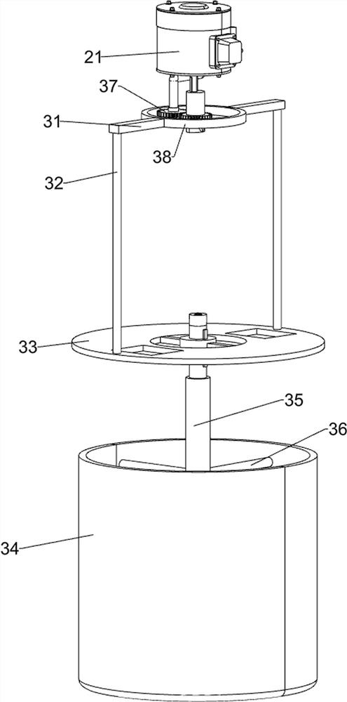
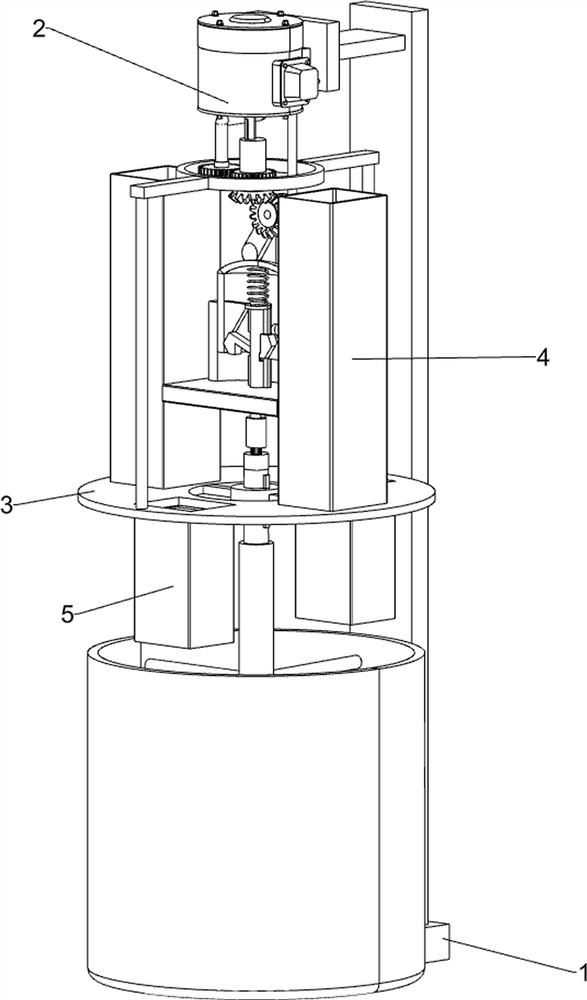
[0018] A material automatic mixing mixer, such as Figure 1-3 As shown, it includes a support 1, a lifting assembly 2 and a stirring assembly 3. The lifting assembly 2 is installed on the front side of the top of the support 1 for lifting and lowering by rotation, and the stirring assembly 3 for stirring by rotating is installed below the lifting assembly 2.
[0019] When it is necessary to use the device to mix materials, first pour the materials to be mixed into the mixing component 3, then control the lifting component 2 to start working, the lifting component 2 drives the stirring component 3 to start working, and the materials are mixed. After finishing, control lifting assembly 2 to stop working.
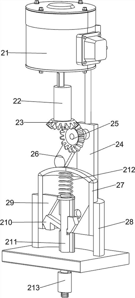
[0020] The lifting assembly 2 includes a reduction motor 21, a rotating shaft 22, a first bevel gear 23, a first connecting plate 24, a second bevel gear 25, a push block 26, a sliding cylinder 27, a mounting plate 28, a wedge block 29, and a push block 210 , connecting rod 2...
Embodiment 2
[0025] On the basis of Example 1, such as figure 1 As shown, the rotating rod 35 can only slide up and down on the connecting plate 33 and cannot rotate, and the top of the rotating rod 35 is connected with the connecting rod 211 through the rotating joint 213 .
[0026] Because the rotating rod 35 needs to move up and down with the connecting rod 211, so the connecting rod 211 can move up and down, and simultaneously because of the swivel joint 213, so the rotating rod 35 can also rotate.
[0027] It also includes a material storage pipe 4 and a feeding pipe 5, the left and right sides of the mounting plate 28 are fixedly connected with the material storage pipe 4 by bolts, the bottom of the material storage pipe 4 cooperates with the connection plate 33, and the bottom of the connection plate 33 is equipped with a discharge pipe 5.
[0028] When the material is mixed, the material can be put into the storage pipe 4, and when the connecting plate 33 rotates, it drives the fe...
PUM
Abstract
The invention relates to a stirrer, in particular to an automatic material mixing stirrer. The technical problem to be solved is to provide an automatic material mixing stirrer which can automaticallyadd materials for mixing and increase the mixing speed. The automatic material mixing stirrer comprises a support; a lifting assembly which is installed on the support and ascends and descends in a rotating mode; and a stirring assembly which is installed on the lifting assembly and conducts stirring in a rotating mode. Through mixing of the lifting assembly and the stirring assembly, a stirringrod can rotate and move up and down at the same time, and material mixing is accelerated. Due to the fact that a rotating rod needs to move up and down along with a connecting rod, the connecting rodcan move up and down, and meanwhile due to a rotating connector, the rotating rod can also rotate. Through the cooperation of a material storagepipe and a discharging pipe, before materials are mixed, the materials can be placed in the material storagepipe, so that the materials can be automatically added, and the equipment is more convenient to use.
Description
technical field [0001] The invention relates to a mixer, in particular to a material automatic mixing mixer. Background technique [0002] Material is a professional term in the field of production in China. It refers to all materials (whether they come from means of production or means of living) that are used by production enterprises to circulate in the field of production other than the final product, such as fuel, parts, semi-finished products, foreign goods, etc. Parts and leftovers, scraps and various wastes that are inevitably generated during the production process are collectively referred to as "materials". When producing products, it is often necessary to mix materials. [0003] At present, when mixing materials, they are mixed by stirring. First, put different types of materials into the container, and then mix by stirring. During the mixing process, it is necessary to continuously add materials. Very inconvenient. [0004] Therefore need to develop a kind of...
Claims
Application Information
Patent Timeline
Application Date:The date an application was filed.
Publication Date:The date a patent or application was officially published.
First Publication Date:The earliest publication date of a patent with the same application number.
Issue Date:Publication date of the patent grant document.
PCT Entry Date:The Entry date of PCT National Phase.
Estimated Expiry Date:The statutory expiry date of a patent right according to the Patent Law, and it is the longest term of protection that the patent right can achieve without the termination of the patent right due to other reasons(Term extension factor has been taken into account ).
Invalid Date:Actual expiry date is based on effective date or publication date of legal transaction data of invalid patent.

