
Laser cutting device for channel beam

A technology of laser cutting and laser cutting machine, which is applied in the direction of laser welding equipment, welding equipment, metal processing equipment, etc., and can solve the problem of low cutting efficiency of channel beams

Pending Publication Date: 2020-12-25
日照兴业汽车配件股份有限公司
View PDF0 Cites 0 Cited by
  • Summary
  • Abstract
  • Description
  • Claims
  • Application Information

AI Technical Summary

Problems solved by technology

[0003] In view of the above defects, the object of the present invention is to provide a laser cutting device for channel beams, aiming to solve the technical problem of low channel beam cutting efficiency in the prior art

Method used


Image

  • Laser cutting device for channel beam
  • Laser cutting device for channel beam
  • Laser cutting device for channel beam

Examples


Embodiment Construction

[0033] Below in conjunction with accompanying drawing, further elaborate the present invention.

[0034] The orientations involved in this manual are all based on the orientation of a laser cutting device for channel beams of the present invention when it is working normally, and do not limit its orientation during storage and transportation, and only represent relative positional relationships, not absolute ones. Positional relationship.

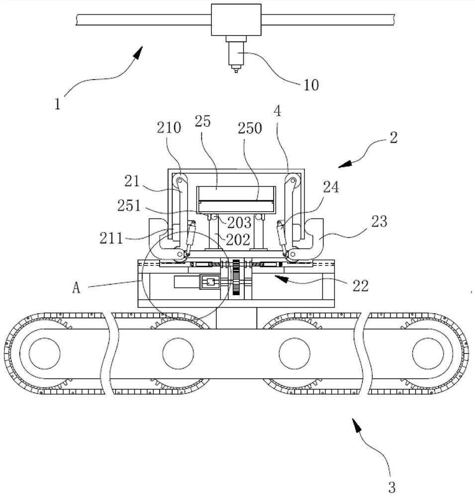
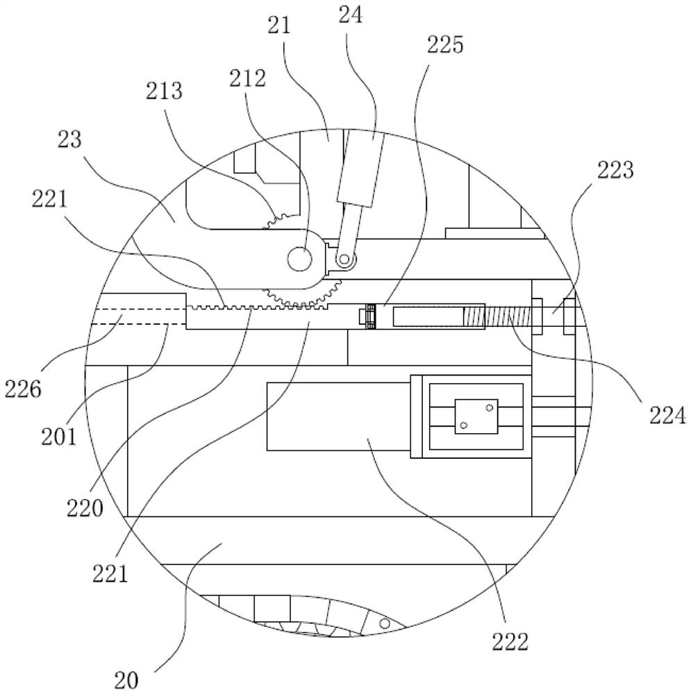
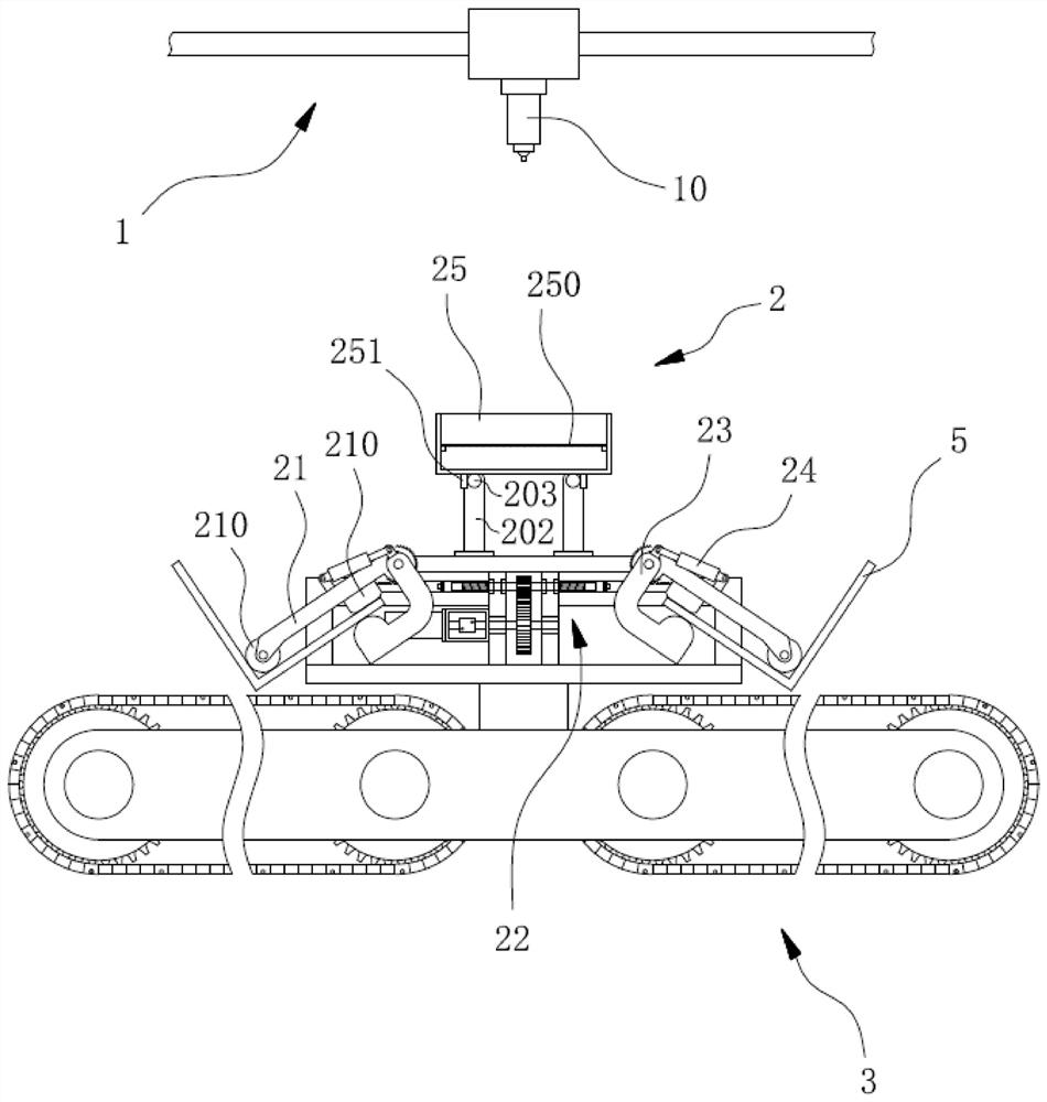
[0035] like figure 1 , figure 2 , image 3 as well as Figure 4 Commonly shown, the laser cutting device used for the channel beam 4 includes a cutting seat 2, and a laser cutting machine 1 is arranged above the cutting seat 2. The laser cutting machine 1 includes a gantry frame, and the gantry frame is equipped with a moving mechanism in the X direction and a moving mechanism in the Y direction. The laser head 10 jointly driven by the moving mechanism and the Z-direction moving mechanism faces the cutting seat 2 facing downward.

[0...


PUM


Abstract

The invention discloses a laser cutting device for a channel beam, and relates to the technical field of laser cutting equipment. The laser cutting device comprises a cutting seat; a laser cutting machine is arranged above the cutting seat; conveying devices are arranged on the two sides below the cutting seat; the cutting seat comprises a base, two first swinging arms are symmetrically installedat the top of the base, and first driving mechanisms for driving the two first swinging arms to swing towards each other or away from each other are arranged in the base; a second swinging arm and a second driving mechanism are installed on each first swinging arm; and the second driving mechanisms drive the second swinging arms to swing towards the outer sides of the first swinging arms or away from the outer sides of the first swinging arms. According to the laser cutting device, the technical problem of low cutting efficiency of the channel beam in the prior art is solved, rapid clamping and cutting of the channel beam and respective transferring of L-shaped plates formed through cutting are achieved, and the production efficiency is improved. Meanwhile, the laser cutting device has theadvantages of convenience in use and high mechanism stability.

Description

technical field [0001] The invention relates to the technical field of laser cutting equipment, in particular to a laser cutting device for channel beams. Background technique [0002] The segmented channel beam is laser cut into two L-shaped plates along the middle, and the L-shaped plate is used to manufacture the connecting plate of the frame. At present, the channel beam is cut by a chuck to fix it, and the L-shaped plate formed after laser cutting The plate is manually removed, which makes the clamping efficiency of the channel beam low, and the blanking and transfer of the L-shaped plate cannot be automated. Contents of the invention [0003] In view of the above defects, the object of the present invention is to provide a laser cutting device for channel beams, aiming to solve the technical problem of low channel beam cutting efficiency in the prior art. [0004] In order to solve the problems of the technologies described above, the technical solution of the prese...

Claims


Application Information

Patent Timeline
Patent Type & Authority Applications(China)
IPC IPC(8): B23K26/38B23K26/70B23K26/02
CPCB23K26/02B23K26/38B23K26/702
Inventor 张玉奎
Owner 日照兴业汽车配件股份有限公司
Learn More