Assembling device and method for power battery module

A technology for assembling devices and power batteries, which is applied in the direction of auxiliary devices, battery assembling machines, secondary battery manufacturing, etc., can solve the problems of reducing the scope of application, battery damage, and easy tilting of the battery, so as to improve the scope of application and extend the service life , mobile operation smooth effect

Active Publication Date: 2020-12-25
安徽浩瀚星宇新能源科技有限公司
View PDF10 Cites 5 Cited by
  • Summary
  • Abstract
  • Description
  • Claims
  • Application Information

AI Technical Summary

Problems solved by technology

[0005] In order to overcome the fact that the traditional power battery module assembly device does not have a mobile adjustment structure, the traditional power battery module assembly device can only assemble and process batteries of a fixed type, which reduces its scope of application; at the same time, the traditional power battery module assembly The device does not have a side-rotating auxiliary fixing structure, so that the power battery module assembly device cannot perform auxiliary fixing operations on different models, making the battery prone to tilting during the assembly process; secondly, the traditional power battery module assembly device does not have buffer protection The structure makes it easy to cause certain damage to the battery during the battery assembly process of the power battery module assembly device, which reduces the use effect of the power battery module assembly device, and provides a power battery module assembly device

Method used


Image

  • Assembling device and method for power battery module
  • Assembling device and method for power battery module
  • Assembling device and method for power battery module

Examples


Embodiment Construction

[0033] The technical solutions in the embodiments of the present invention will be clearly and completely described below in conjunction with the embodiments of the present invention. Apparently, the described embodiments are only some of the embodiments of the present invention, not all of them. Based on the embodiments of the present invention, all other embodiments obtained by persons of ordinary skill in the art without creative efforts fall within the protection scope of the present invention.

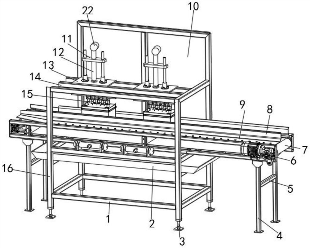
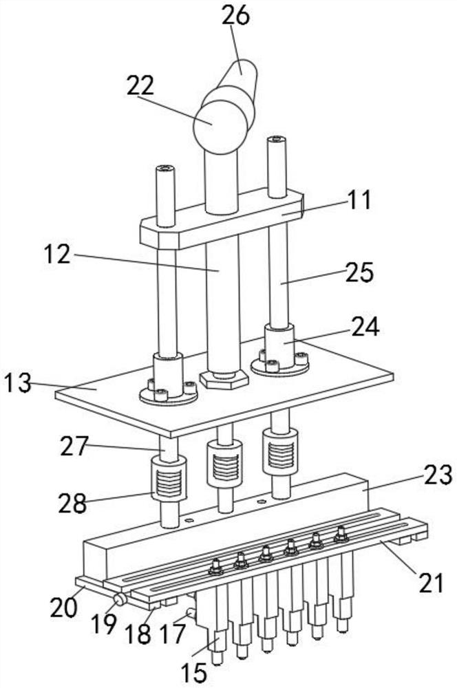
[0034] Such as Figure 1-6 As shown, a power battery module assembly device includes a combination frame 16, a support frame 4, a fixed foot plate 13 and a docking block 23, the support frame 4 is fixedly installed on the inner side of the combination frame 16, and the outer surface of the upper end of the combination frame 16 is fixed Two groups of connecting brackets 14 are installed, and the fixed foot plate 13 is fixedly installed on the outer surface of the upper end of the c...


PUM


Abstract

The invention discloses an assembling device for a power battery module. The assembling device includes a combined frame, a supporting frame, fixed foot plates and a butt joint clamping block; the supporting frame is fixedly mounted on the inner side of the combined frame, two sets of connecting supports are fixedly mounted on the outer surface of the upper end of the combined frame, and the fixedfoot plates are fixedly mounted on the outer surfaces of the upper ends of the connecting supports; and hydraulic rods are fixedly mounted in the middles of the inner sides of the fixed foot plates,fixed side rods are fixedly mounted on positions, close to two sides of the hydraulic rods, at the upper ends of the fixed foot plates, the outer surfaces of the bottoms of the fixed side rods are fixedly sleeved with fixed clamping sleeves, and the fixed side rods are fixedly connected with the fixed foot plates through the fixed clamping sleeves. The assembling device for the power battery module is provided with a movable adjusting structure, so that the application range of the assembling device is widened, and the assembling device is suitable for battery modules of different types; and meanwhile, the assembling device is provided with an auxiliary fixing structure, so that inclination of the battery modules in an assembling process is avoided, and the stability of the battery modulesis improved.

Description

technical field [0001] The invention belongs to the technical field of assembling devices, and more specifically relates to a power battery module assembling device and an assembling method. Background technique [0002] The power battery module assembly device is an assembly device for welding and fixing multiple groups of battery blocks in the power battery module during the processing of the power battery module. The assembly device can shorten the length of the battery block. The time required to connect between. [0003] In the battery assembly device disclosed in the comparative document CN110936002A, a longitudinal displacement mechanism is fixed on the top of one frame body, and a longitudinal displacement linear guide rail is fixed on the top of the other frame body; one end of the lateral displacement mechanism is installed on the slider of the longitudinal displacement mechanism, The other end is fixed on the slider of the longitudinal displacement linear guide r...

Claims


Application Information

Patent Timeline
Patent Type & Authority Applications(China)
IPC IPC(8): B23K37/00B23K37/02B23K37/04B23K31/02H01M10/04
CPCB23K37/00B23K37/0443B23K37/02B23K31/02H01M10/0404B23K2101/36Y02P70/50
Inventor 戴星宇
Owner 安徽浩瀚星宇新能源科技有限公司
Why Eureka
Try Eureka