Rounding machine for wooden pole machining

A technology of wooden pole and circular machine, applied in the direction of circular machine, etc., can solve the problems of low work efficiency and troublesome operation, and achieve the effect of high work efficiency, convenient operation and convenient collection.

Active Publication Date: 2020-12-25
浏阳市美寓木业有限公司
View PDF10 Cites 0 Cited by
  • Summary
  • Abstract
  • Description
  • Claims
  • Application Information

AI Technical Summary

Problems solved by technology

[0005] In order to overcome the need to insert the wooden pole on the machine, and then move the trimming tool on the wooden pole to trim it, the operation is cumbersome, and only one wooden pole can be trimmed at a time, resulting in low work efficiency. Technical problem: provide A rounding machine for wooden pole processing that can replace manual trimming of wooden poles into a cylindrical shape, is easy to operate, can trim six wooden poles at a time, and has high work efficiency

Method used


Image

  • Rounding machine for wooden pole machining
  • Rounding machine for wooden pole machining
  • Rounding machine for wooden pole machining

Examples


Embodiment 1

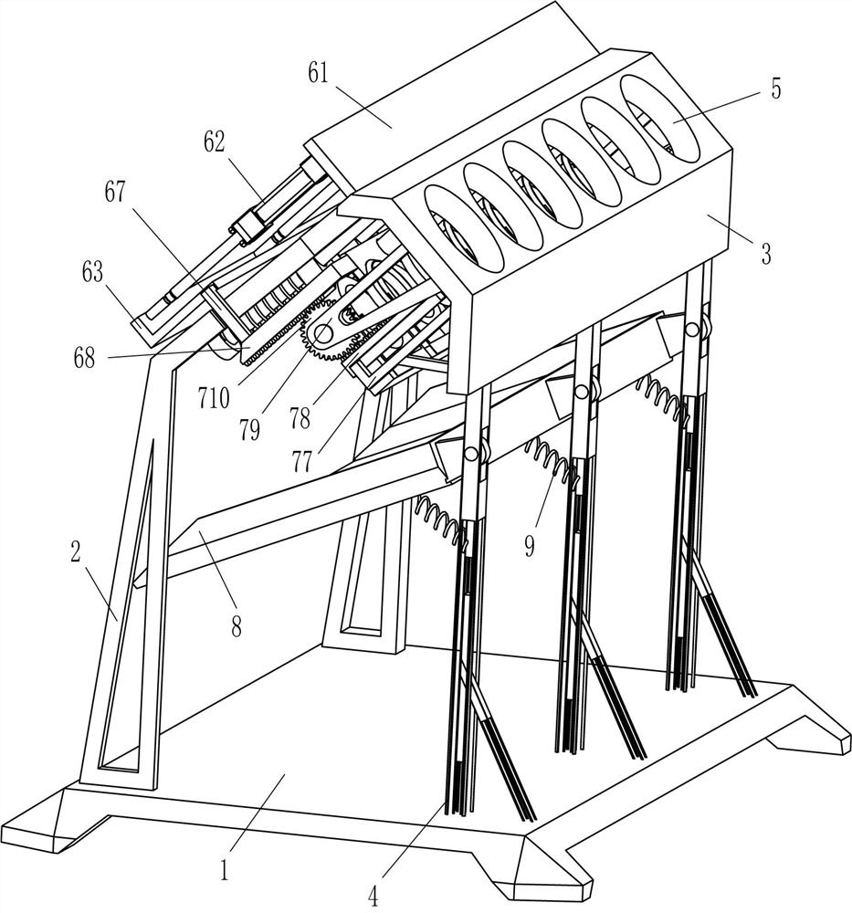
[0021] A rounding machine for wooden rod processing, such as figure 1 and figure 2 As shown, it includes a base 1, an L-shaped bar 2, a special-shaped plate 3, a support bar 4, and a trimming mechanism 6. The back side of the top of the base 1 is evenly spaced with support bars 4, and the tops of the three support bars 4 are fixed with The special-shaped plate 3 has placement holes 5 evenly spaced on the upper part of the rear side of the special-shaped plate 3. The front side of the top of the base 1 is symmetrically fixed with L-shaped rods 2, and the rear end of the L-shaped rod 2 is fixedly connected with the front side of the special-shaped plate 3. A trimming mechanism 6 is provided between the plate 3 and the two L-shaped rods 2 , and the trimming mechanism 6 cooperates with the placement hole 5 .

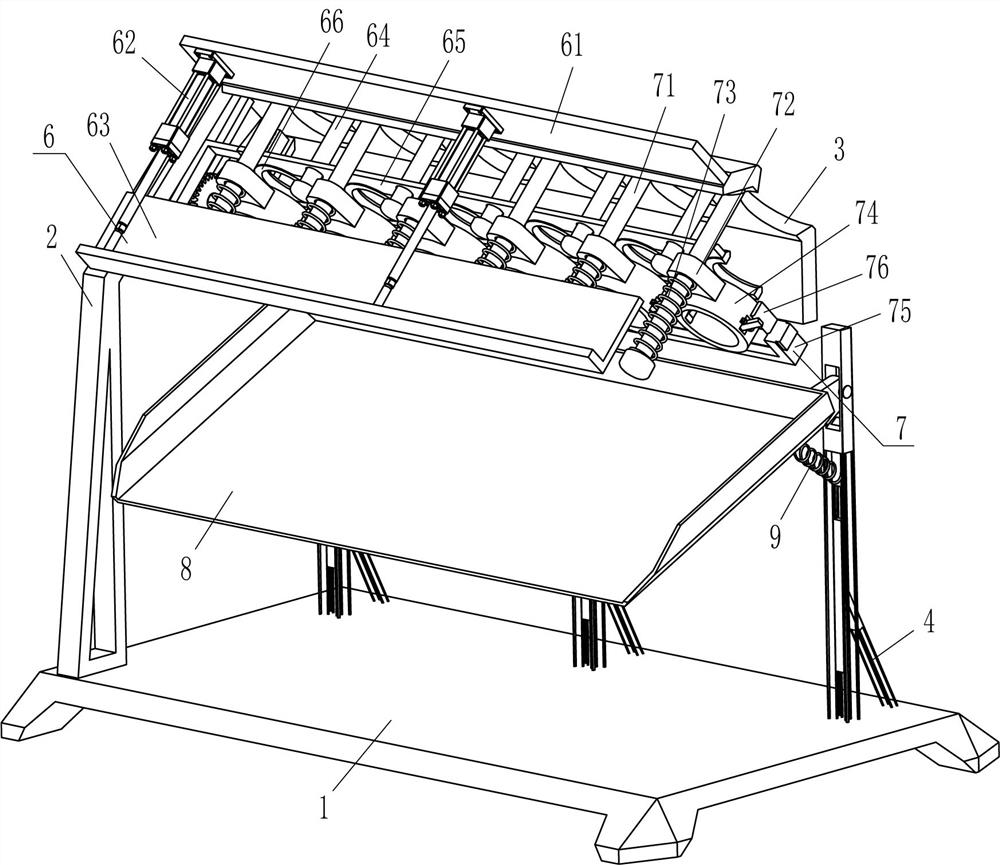
[0022] The trimming mechanism 6 includes a fixed plate 61, a cylinder 62, an L-shaped plate 63, a guide rod 64, a movable plate 65, an annular cutter 66, a sliding plate 6...

Embodiment 2

[0026] On the basis of Example 1, such as Figure 1-Figure 3As shown, a clamping mechanism 7 is also included, and the clamping mechanism 7 includes a guide rod 71, a sliding sleeve 72, a first spring 73, an annular sleeve 74, a u-shaped plate 75, a u-shaped mounting plate 76, a guide frame 77, the first Two racks 78, mounting frame 79, gear 710, clamping bar 711 and second spring 712, six guide bars 71 are fixedly connected evenly spaced in the top of special-shaped plate 3, and the sliding type on guide bar 71 is provided with sliding sleeve 72, A first spring 73 is wound around the front side of the sliding sleeve 72 and the front end of the guide rod 71, and the bottom of the sliding sleeve 72 is fixedly connected with an annular sleeve 74. The annular sleeve 74 corresponds to the annular cutter 66, and the left and right sides of the annular sleeve 74 are rotated. There is a clamping rod 711 in the piercing type, and a second spring 712 is connected between the inner side...

Embodiment 3

[0029] On the basis of embodiment 1 and embodiment 2, such as figure 1 and image 3 As shown, it also includes an oblique frame 8 and a third spring 9, an oblique frame 8 is hinged between the upper parts of the front sides of the three support rods 4, and an oblique frame 8 is connected between the rear side of the outer bottom of the oblique frame 8 and the upper parts of the front sides of the three support rods 4. The third spring 9.

[0030] It also includes a rubber sleeve 10, and the inner end of the clamping rod 711 is fixedly connected with the rubber sleeve 10.

[0031] Firstly, the operator places the collection container under the front side of the inclined frame 8, and when the cylindrical wooden pole falls from the annular sleeve 74, the wooden pole falls onto the inclined frame 8, and due to the action of the third spring 9, The inclined frame 8 buffers the wooden rod, and the buffered wooden rod slides from the inclined frame 8 into the collection container. ...


PUM


Abstract

The invention relates to a rounding machine, in particular to a rounding machine for wooden pole machining. The technical problem is how to design the rounding machine for the wooden pole machining which can replace manpower to trim wooden poles into a cylindrical shape, is convenient to operate, can trim six wooden poles at a time and is high in working efficiency. The rounding machine for the wooden pole machining comprises a base, supporting rods are fixedly connected to the edge of one side of the base at intervals, and the number of the supporting rods is three; and a special-shaped platefixedly connected among the ends, away from the base, of the three supporting rods, and placing holes are arranged at one side of the special-shaped plate at intervals. According to the rounding machine for the wooden pole machining provided by the invention, six wooden poles are placed in the placing holes to make contact with an annular cutter, an telescopic rod of an air cylinder is started tocontinuously stretch out and draw back, the annular cutter can move up and down to trim the wooden poles, the wooden poles are trimmed into the cylindrical shape, a trimming tool does not need to bemanually arranged on the wooden poles in a sleeved mode to move to trim the wooden poles, operation is convenient, and the working efficiency is high.

Description

technical field [0001] The invention relates to a rounding machine, in particular to a rounding machine for wood pole processing. Background technique [0002] Wooden pole: A slender piece of wood or something similar for a certain purpose. In the process of making wooden poles, the wooden poles are all square at the beginning, and the wooden poles need to be trimmed into a round shape to facilitate subsequent use. [0003] At present, most of the wooden poles are trimmed into a cylindrical shape manually and with machines. First, people insert the wooden poles on the rotating machine, then put the trimming tool on the wooden poles, start the rotating machine to drive the wooden poles to rotate, and pull the trimming. The tool can be trimmed into a cylindrical shape by moving the wooden pole, which is cumbersome to operate, and only one wooden pole can be trimmed into a cylindrical shape at a time, resulting in low work efficiency. [0004] Therefore, it is necessary to des...

Claims


Application Information

Patent Timeline
Patent Type & Authority Applications(China)
IPC IPC(8): B27C5/08
CPCB27C5/08
Inventor 余杰
Owner 浏阳市美寓木业有限公司
Why Eureka
Try Eureka