A rounding machine for wood rod processing
A technology of wooden pole and circular machine, applied in the direction of circular machine, etc., can solve the problems of low work efficiency and troublesome operation, and achieve the effect of high work efficiency, convenient operation and convenient collection.
- Summary
- Abstract
- Description
- Claims
- Application Information
AI Technical Summary
Problems solved by technology
Method used
Image
Examples
Embodiment 1
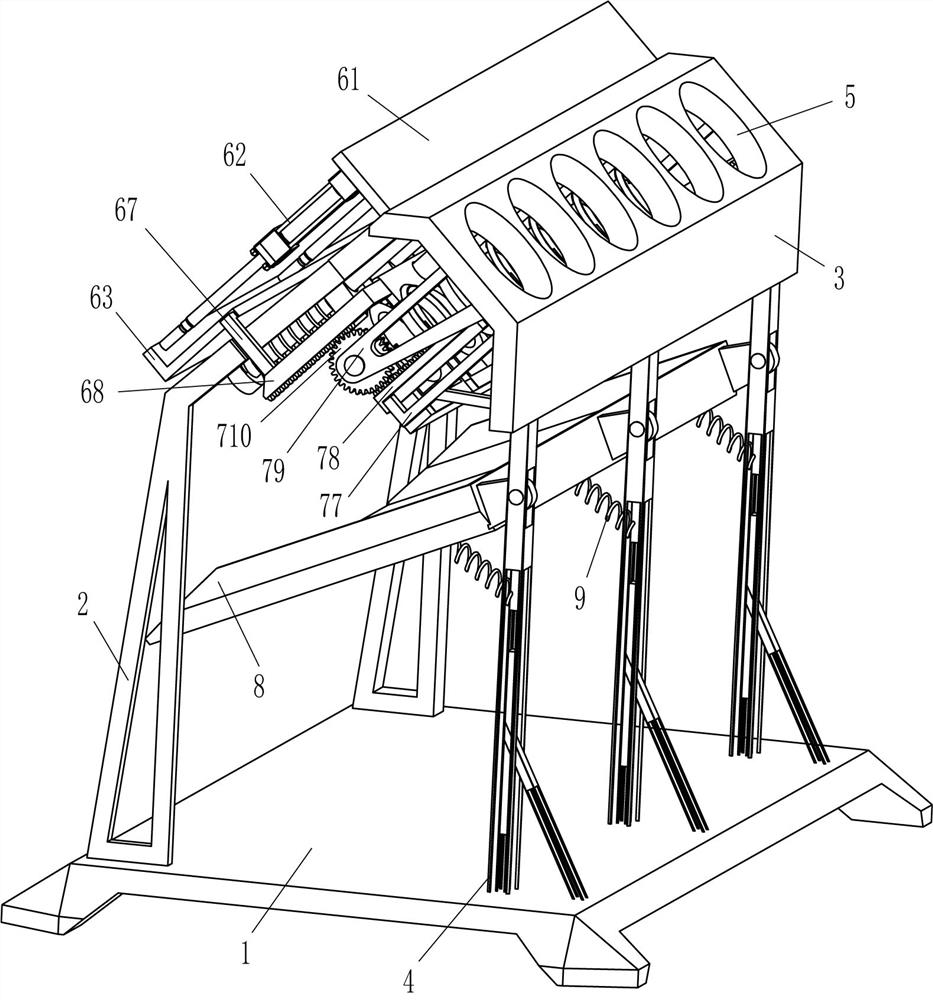
[0021] A rounding machine for wood rod processing, such as figure 1 and figure 2 As shown, it includes a base 1, an L-shaped rod 2, a special-shaped plate 3, a support rod 4 and a trimming mechanism 6. A support rod 4 is fixedly connected to the rear side of the top of the base 1 evenly spaced, and a support rod 4 is fixed between the tops of the three support rods 4. Special-shaped plate 3, there are placement holes 5 evenly spaced on the upper part of the rear side of the special-shaped plate 3, and L-shaped rods 2 are fixed symmetrically on the front side of the top of the base 1, and the rear end of the L-shaped rod 2 is fixedly connected with the front side of the special-shaped plate 3. A trimming mechanism 6 is arranged between the plate 3 and the two L-shaped rods 2 , and the trimming mechanism 6 is matched with the placement hole 5 .
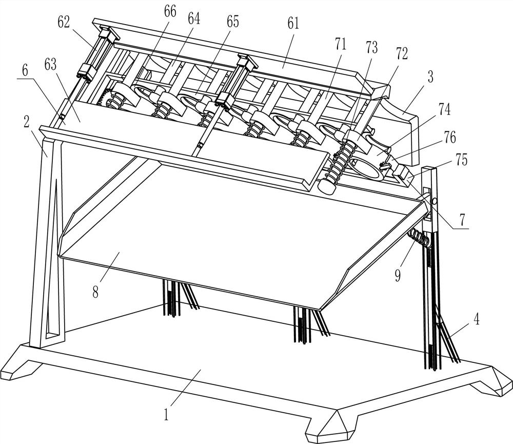
[0022] The trimming mechanism 6 includes a fixed plate 61, a cylinder 62, an L-shaped plate 63, a guide rod 64, a movable plate 65, ...
Embodiment 2
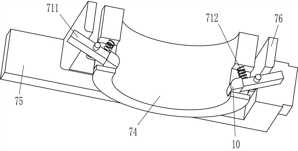
[0026] On the basis of Example 1, as Figure 1-Figure 3As shown, it also includes a clamping mechanism 7. The clamping mechanism 7 includes a guide rod 71, a sliding sleeve 72, a first spring 73, an annular sleeve 74, a u-shaped plate 75, a u-shaped mounting plate 76, a guide frame 77, a first The second rack 78, the mounting frame 79, the gear 710, the clamping rod 711 and the second spring 712, six guide rods 71 are fixedly connected to the top of the special-shaped plate 3 at even intervals, and the guide rods 71 are provided with sliding sleeves 72. A first spring 73 is wound between the front side of the sliding sleeve 72 and the front end of the guide rod 71, and an annular sleeve 74 is fixedly connected to the bottom of the sliding sleeve 72. The annular sleeve 74 corresponds to the annular cutter 66, and both the left and right sides of the annular sleeve 74 rotate. A clamp rod 711 is connected to the inner side of the clamp rod 711, and a second spring 712 is conn...
Embodiment 3
[0029] On the basis of Example 1 and Example 2, as figure 1 and image 3 As shown, it also includes an inclined frame 8 and a third spring 9, an inclined frame 8 is hinged between the upper parts of the front sides of the three support rods 4, and the rear side of the outer bottom of the inclined frame 8 is connected with the upper parts of the front sides of the three support rods 4. The third spring 9 .
[0030] A rubber sleeve 10 is also included, and the inner end of the clamp rod 711 is fixedly connected with the rubber sleeve 10 .
[0031] First, the operator places the collection container under the front side of the inclined frame 8. When the cylindrical wooden rod is dropped from the annular sleeve 74, the wooden rod falls onto the inclined frame 8. Due to the action of the third spring 9, The inclined frame 8 buffers the wooden poles, and the buffered wooden poles slide down from the inclined frame 8 into the collection container. In this way, it is more convenien...
PUM
 Abstract
Description
Claims
Application Information
 - R&D
- Intellectual Property
- Life Sciences
- Materials
- Tech Scout
- Unparalleled Data Quality
- Higher Quality Content
- 60% Fewer Hallucinations
Browse by: Latest US Patents, China's latest patents, Technical Efficacy Thesaurus, Application Domain, Technology Topic, Popular Technical Reports.
© 2025 PatSnap. All rights reserved.Legal|Privacy policy|Modern Slavery Act Transparency Statement|Sitemap|About US| Contact US: help@patsnap.com


