Thermal compounding device and thermal compounding method

A technology of thermal compounding and reverse direction, which is applied in other household appliances, sustainable manufacturing/processing, climate sustainability, etc., can solve problems such as uneven temperature and pressure distribution, dislocation of composite units, product scrapping, etc., and achieve easy solution Fracturing issues, enhanced thermal compounding effects, improved preheating effects

Pending Publication Date: 2020-12-25
海目星激光智能装备(江苏)有限公司 +1
View PDF0 Cites 2 Cited by
  • Summary
  • Abstract
  • Description
  • Claims
  • Application Information

AI Technical Summary

Problems solved by technology

The traditional thermal lamination process generally adopts multi-roller hot pressing or the lamination process of rolling the lamination unit after passing through the oven. In production practice, uneven hot pressing, uneven distribution of temperature and pressure often occur, thus It causes dislocation of the composite unit and easy cracking of the end face; in addition, since the thermal composite process is thermally composited with the positive and negative electrodes and diaphragms that have been composited, the scrapping of the product in the thermal composite process will result in the scrapping of multiple incoming materials, and the resulting cost very big loss

Method used


Image

  • Thermal compounding device and thermal compounding method
  • Thermal compounding device and thermal compounding method

Examples


Embodiment Construction

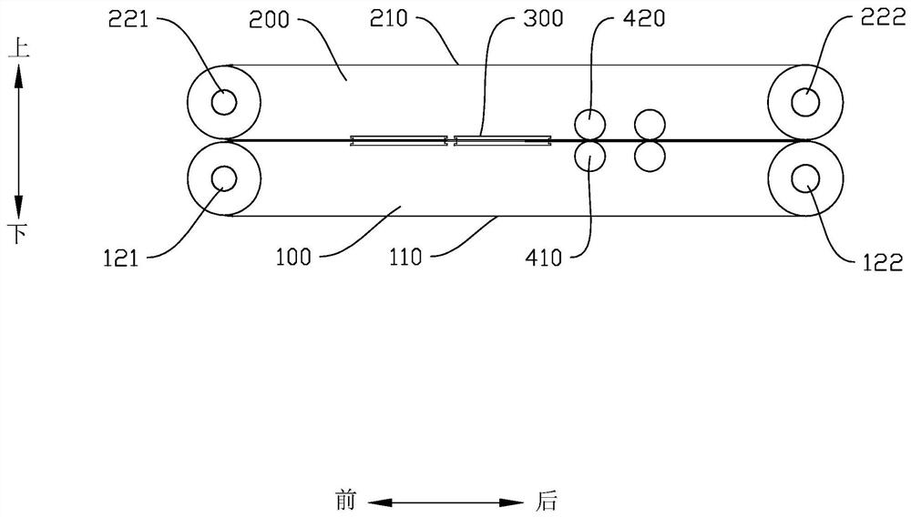
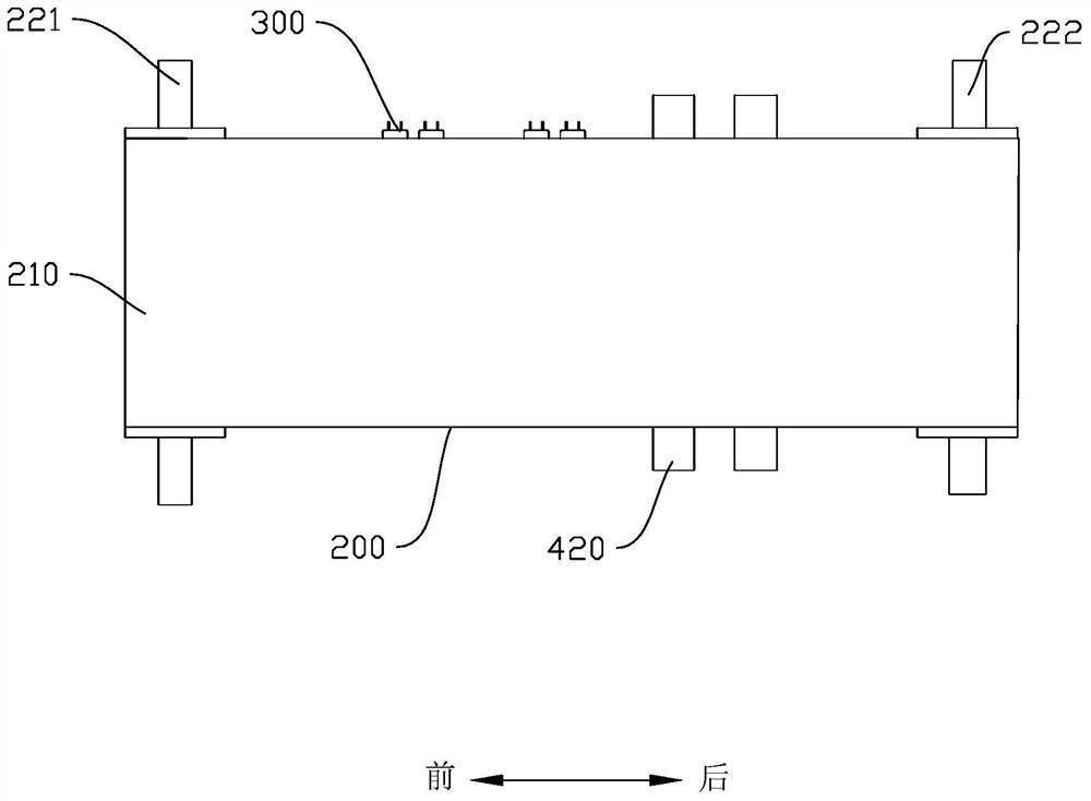
[0036] Embodiments of the present invention are described in detail below, and examples of the embodiments are shown in the drawings, wherein the same or similar reference numerals denote the same or similar elements or elements having the same or similar functions throughout. The embodiments described below by referring to the figures are exemplary only for explaining the present invention and should not be construed as limiting the present invention.

[0037] In the description of the present invention, it should be understood that the orientation descriptions, such as up, down, left, right, front, back, etc. indicated orientations or positional relationships are based on the orientations or positional relationships shown in the drawings, and are only In order to facilitate the description of the present invention and simplify the description, it does not indicate or imply that the device or element referred to must have a specific orientation, be constructed and operated in ...


PUM


Abstract

The invention discloses a thermal compounding device and a thermal compounding method. The thermal compounding device comprises a first transmission mechanism, a second transmission mechanism, a heating assembly, force application assemblies and a control mechanism; the first transmission mechanism comprises a first conveying assembly and a first driving assembly, the second transmission mechanismis arranged above the first transmission mechanism in parallel, the second transmission mechanism comprises a second conveying assembly and a second driving assembly, the second transmission mechanism and the first transmission mechanism rotate in opposite directions, a preheating press-fit channel allowing the composite unit to pass through is formed between the second transmission mechanism andthe first transmission mechanism; the heating assembly is used for heating the first conveying assembly and the second conveying assembly; the force application assemblies are arranged on the inner sides of the opposite faces of the first conveying assembly and the second conveying assembly correspondingly; and the control mechanism is electrically connected with the first driving assembly, the second driving assembly, the heating assembly and the force application assemblies correspondingly. According to the thermal compounding device and the thermal compounding method, dislocation and cracking of the composite unit can be avoided, the reject ratio is reduced, and therefore the cost is reduced.

Description

technical field [0001] The invention relates to the technical field of battery manufacturing, in particular to a heat compound device and a method thereof. Background technique [0002] The thermal lamination process mainly refers to the process of bonding the positive and negative materials of the lithium battery and the diaphragm (ie, the composite unit) after heating. The traditional thermal lamination process generally adopts multi-roller hot pressing or the lamination process of rolling the lamination unit after passing through the oven. In production practice, uneven hot pressing, uneven distribution of temperature and pressure often occur, thus It causes dislocation of the composite unit and easy cracking of the end face; in addition, since the thermal composite process is thermally composited by the positive and negative electrodes and separators that have been composited, the scrapping of the product in the thermal composite process will result in the scrapping of m...

Claims


Application Information

Patent Timeline
IPC IPC(8): B29C65/64B29C65/02B29C65/78H01M10/058B29L31/34
CPCB29C65/02B29C65/64B29C65/7841B29C65/7858B29L2031/3468H01M10/058Y02E60/10Y02P70/50
Inventor 赵盛宇张松岭荣超超胡正江谷德吉邓玮龙蓉温燕修赵浪赵凯江新海
Owner 海目星激光智能装备(江苏)有限公司
Why Eureka
Try Eureka