Efficient and safe regenerative combustion VOCs purification system

A technology of regenerative combustion and purification system, applied in combustion type, combustion method, incinerator, etc., can solve problems such as poor continuity, interruption of organic waste gas treatment process, catalyst deactivation, etc., to improve preheating effect and high degree of automation , to ensure the effect of continuity

Active Publication Date: 2021-01-26
南大恩洁优环境技术江苏股份公司
View PDF12 Cites 4 Cited by
  • Summary
  • Abstract
  • Description
  • Claims
  • Application Information

AI Technical Summary

Problems solved by technology

[0003] Existing organic waste gas catalytic combustion equipment is mainly composed of heat preservation shell, heat storage body, heat exchanger, integral catalyst, electric heating device, etc. Preheat and reach the catalytic combustion reaction temperature, then the organic waste gas mixed with fresh air is sprayed on the regenerator to preheat the mixed gas, and then the mixed gas is sprayed on the surface of the monolithic catalyst for catalytic combustion reaction to realize the The purpose of purifying organic waste gas, but during the catalytic process, carbon deposits will gradually form on the surface of the catalyst, which will cover the catalyst and cause the catalyst to be deactivated, resulting in the catalytic combustion process not being able to proceed normally. Disassemble and remove the carbon deposits on the surface of the monolithic catalyst by roasting, which will not only interrupt the treatment process of organic waste gas, and the continuity will be poor, but also the process of disassembling the monolithic catalyst is complicated, time-consuming and laborious, so it is urgent to design a An efficient and safe regenerative combustion VOCs purification system

Method used


Image

  • Efficient and safe regenerative combustion VOCs purification system
  • Efficient and safe regenerative combustion VOCs purification system
  • Efficient and safe regenerative combustion VOCs purification system

Examples


Embodiment Construction

[0035] The technical solutions in the embodiments of the present invention will be clearly and completely described below in conjunction with the accompanying drawings in the embodiments of the present invention; obviously, the described embodiments are only some embodiments of the present invention; rather than all embodiments. Based on the embodiments of the present invention; all other embodiments obtained by persons of ordinary skill in the art without creative work; all belong to the protection scope of the present invention.

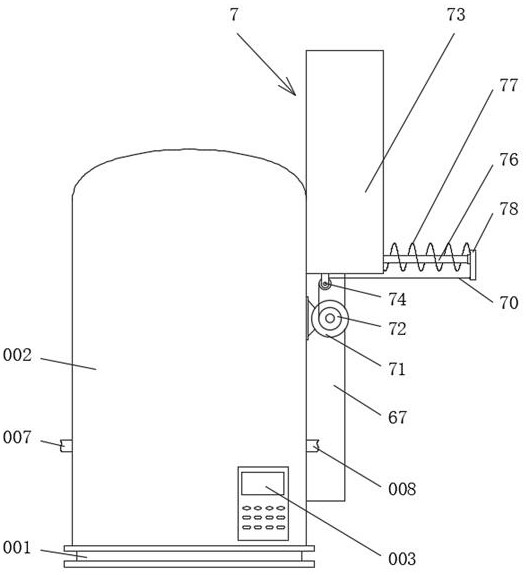
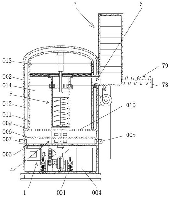
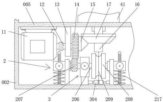
[0036] see Figure 1-14 , an efficient and safe regenerative combustion VOCs purification system, comprising a base 001, a housing 002 is fixedly installed on the top surface of the base 001, a control panel 003 is fixedly installed on the front of the housing 002, and a control panel 003 is fixedly installed on the bottom surface of the inner cavity of the housing 002 There is a control module 004, a lift limit device 2 is provided on the bottom s...


PUM


Abstract

The invention discloses an efficient and safe regenerative combustion VOCs purification system. The efficient and safe regenerative combustion VOCs purification system comprises a base, wherein a shell is fixedly installed on the top surface of the base, and a control panel is fixedly installed on the obverse side of the shell. The inlet air flow and the outlet air flow are separated through a flow guide device, the inlet air flow and the outlet air flow cannot be mixed with each other, meanwhile, the flow guide device can transmit the heat of the outlet air flow to the inlet air flow, and thepreheating effect on the inlet air flow is improved. By means of the cooperation of the control panel, a control module, a driving device, a lifting limiting device, a locking device, a rotating device, a conveying device and a pushing device, a sector-shaped catalyst block is automatically replaced in a non-stop mode, and therefore the continuity of the volatile organic chemical treatment process is ensured, manual participation is not required in the sector-shaped catalyst block replacing process, the time and the labor are saved, the automation degree is high, and the practicability of theefficient and safe regenerative combustion VOCs purification system is improved.

Description

technical field [0001] The invention relates to the field of VOCs purification systems, and more specifically, relates to an efficient and safe regenerative combustion VOCs purification system. Background technique [0002] Organic waste gas, also known as VOCs gas, is flammable, explosive, toxic and harmful, soluble in organic solvents, and difficult to treat. Activated carbon adsorption treatment, catalytic combustion, catalytic oxidation, acid Alkali neutralization method, plasma method and other methods, among which the catalytic combustion method is to use a suitable catalyst in the system to oxidize and decompose the C and H compounds in the exhaust gas into carbon dioxide and water at a lower temperature. The catalytic combustion technology is A new technology emerged under the increasingly urgent situation of environmental protection and energy saving. The main advantages of this method are low ignition temperature, low energy consumption, high treatment efficiency, ...

Claims


Application Information

Patent Timeline
Patent Type & Authority Applications(China)
IPC IPC(8): F23G5/44F23G5/46F23G5/50F23G7/07
CPCF23G5/44F23G5/46F23G5/50F23G7/07
Inventor 陆朝阳李明张纪文徐遵主张波金小贤
Owner 南大恩洁优环境技术江苏股份公司
Why Eureka
Try Eureka