Catalytic converter

a catalytic converter and converter technology, applied in the field of catalytic converters, can solve the problems of insufficient use of catalysts of the whole substrate, insufficient use of exhaust gas in surrounding areas, and insufficient use of area, so as to improve the activity of honeycomb catalysts, and improve the effect of thermal shock performan

Active Publication Date: 2016-05-31
TOYOTA JIDOSHA KK +1
View PDF7 Cites 3 Cited by
  • Summary
  • Abstract
  • Description
  • Claims
  • Application Information

AI Technical Summary

Benefits of technology

[0017]The present disclosure provides a catalytic converter, which has a high warming-up performance after the starting of the engine, and has excellent exhaust gas purification performance by effectively utilize the whole catalyst.
[0019]The catalytic converter is a tandem-type catalytic converter which has two cell structured substrates, i.e., the first and the second substrates, from the upstream side of exhaust gas flow in sequence; in which the first substrate utilizes a substrate that has a uniform cell density, and the second substrate positioned at the downstream side is a substrate in which the center area has a relatively high cell density with respect to a surrounding area. Through this configuration, one of the substrates has a uniform cell density, thus, comparing with the embodiment that both of the two substrates change the cell density, it has the advantage of being easy to be manufactured. Furthermore, the flow rate distribution of the exhaust gas in the cross section of the second substrate positioned at the downstream side can be eased as much as possible to achieve uniformization, thus, the above effect can also influence the first substrate positioned at the upstream side, the flow rate distribution of the exhaust gas in the cross section of the first substrate can also be eased as much as possible to achieve uniformization. As a result, all catalysts in the first and second substrates can be effectively used, the exhaust gas purification performance can be improved.
[0020]Herein, for two tandem-type substrates, by changing the cell density in the cross section of the substrate at the downstream side, the uniformization of flow rate distribution of exhaust gas can be achieved, and above effect can also influence the uniformization of flow rate distribution of exhaust gas in the substrate positioned at the upstream side with a uniform cell density, such effect is the novel effect achieved by the above catalytic converter.
[0021]In addition, since the cell density of the substrate positioned at the upstream side is uniform, for example, since the center area does not have a high cell density, a rising of pressure loss to the exhaust gas flow of the substrate at the upstream side where the exhaust initially flows in is restrained, an excellent exhaust gas flow and an excellent heat supply to the catalytic converter are guaranteed, and a high warming-up performance after the starting of the engine is guaranteed.
[0025]The above catalytic converter is preferred to have a cordierite honeycomb support with excellent anti-thermal-shock performance; otherwise it may be an electrically heated catalytic converter (EHC). The electrically heated catalytic converter is such a catalytic converter, for example, installs a pair of electrodes on the honeycomb catalyst, the electrodes are energized to the heat honeycomb catalyst, to improve the activity of the honeycomb catalyst and further to neutralize the exhaust gas passing through the catalytic converter, by applying the above catalytic converter to a gas exhaust system connecting an automobile engine and a muffler, thus, in addition to purifying the exhaust gas at room temperature, the catalyst can be activated by electrically heating to purify the exhaust gas when it is cold.
[0026]As can be acknowledged from the above description, according to the above catalytic converter, the catalytic converter of an aspect of the present disclosure relates to a catalytic converter, in which a first substrate at a upstream side of the exhaust gas flow and a second substrate at a downstream side of the exhaust gas flow are mounted in tandem, and the cell density of the first substrate is uniform, and the second substrate includes a center area with a relatively high cell density and a surrounding area with a relatively low cell density, thus, an excellent flow of the exhaust gas to the catalytic converter can be guaranteed, the heat supply to the catalytic converter can be promoted, the warming-up performance after the starting of the engine can be increased, and a cold emission reduction effect can be improved. In addition, only the cell density in the cross section of the second substrate at the downstream side changes, thus, comparing with the embodiment that both of the two substrates change the cell density, it has advantages of being easy to be manufactured. Furthermore, the flow rate distribution of the exhaust gas in the cross section of the second substrate positioned at the downstream side can be eased as much as possible to achieve uniformization, and above effect can influence the first substrate positioned at the upstream side, the flow rate distribution of the exhaust gas in the cross section of the first substrate can be eased as much as possible to achieve uniformization. As a result, all catalysts in the first and second substrates can be effectively used, to improve the exhaust gas purification performance.

Problems solved by technology

Incidentally, since gas flow normally flows in the substrate with a relatively high flow rate at the center portion of the duct (center portion of the substrate) where there is no friction influence with the wall of the duct H, the problem is that in the cell structured substrate illustrated in FIG. 7, the flow rate distribution of the exhaust gas at the center area of the cross section of substrates K1, K2 is higher compared with that of the surrounding area, resulting in a reduction of exhaust gas amount flowed in the surrounding area, thus the catalyst in such area cannot be sufficiently used, and as a result, catalyst of the whole substrate cannot be sufficiently used.
Furthermore, if the inflow amount of the exhaust gas to the catalytic converter is reduced, the heat supply to the catalytic converter is inevitably reduced, and the warming-up performance after the starting of the engine is reduced.
However, even according to the catalytic converter disclosed by JP 2000-97019 A, it is the same with that disclosed by JP 9-317454 A, since the cell density of the center area of the substrate at the upstream side is high, the problem that the exhaust gas flow is impended and the inflow amount of exhaust gas is reduced still exists.

Method used


Image

  • Catalytic converter
  • Catalytic converter
  • Catalytic converter

Examples


example 1

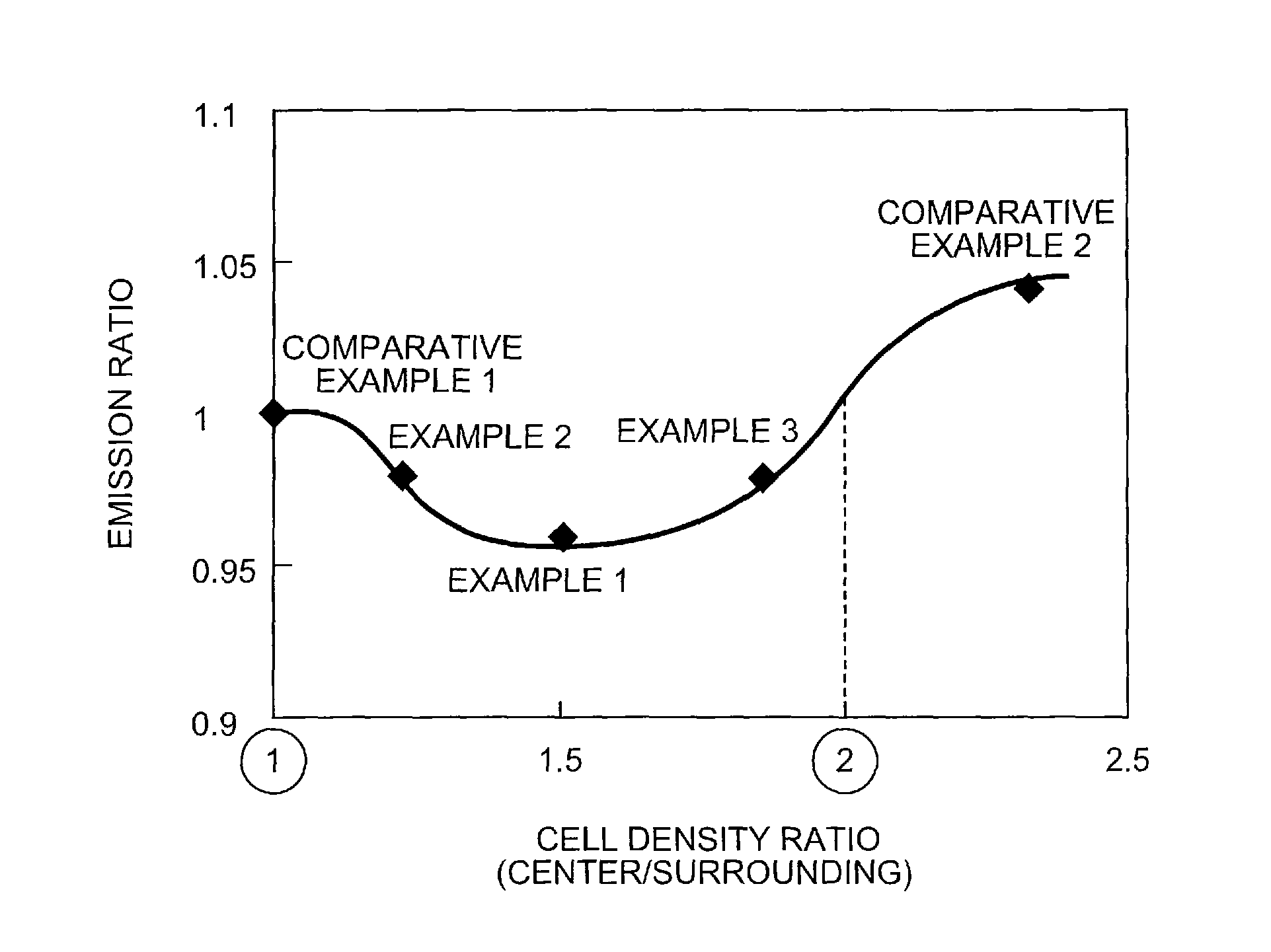
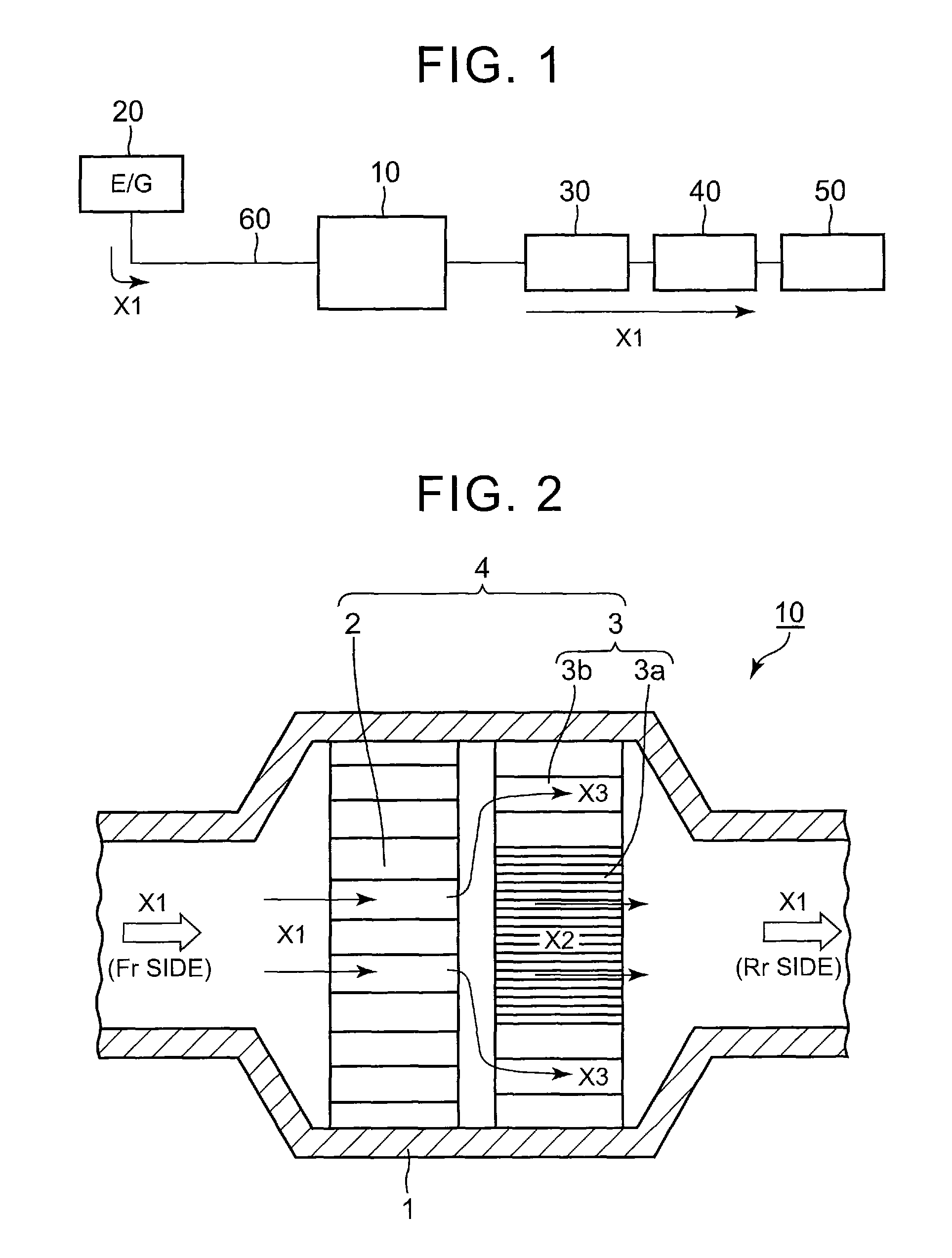
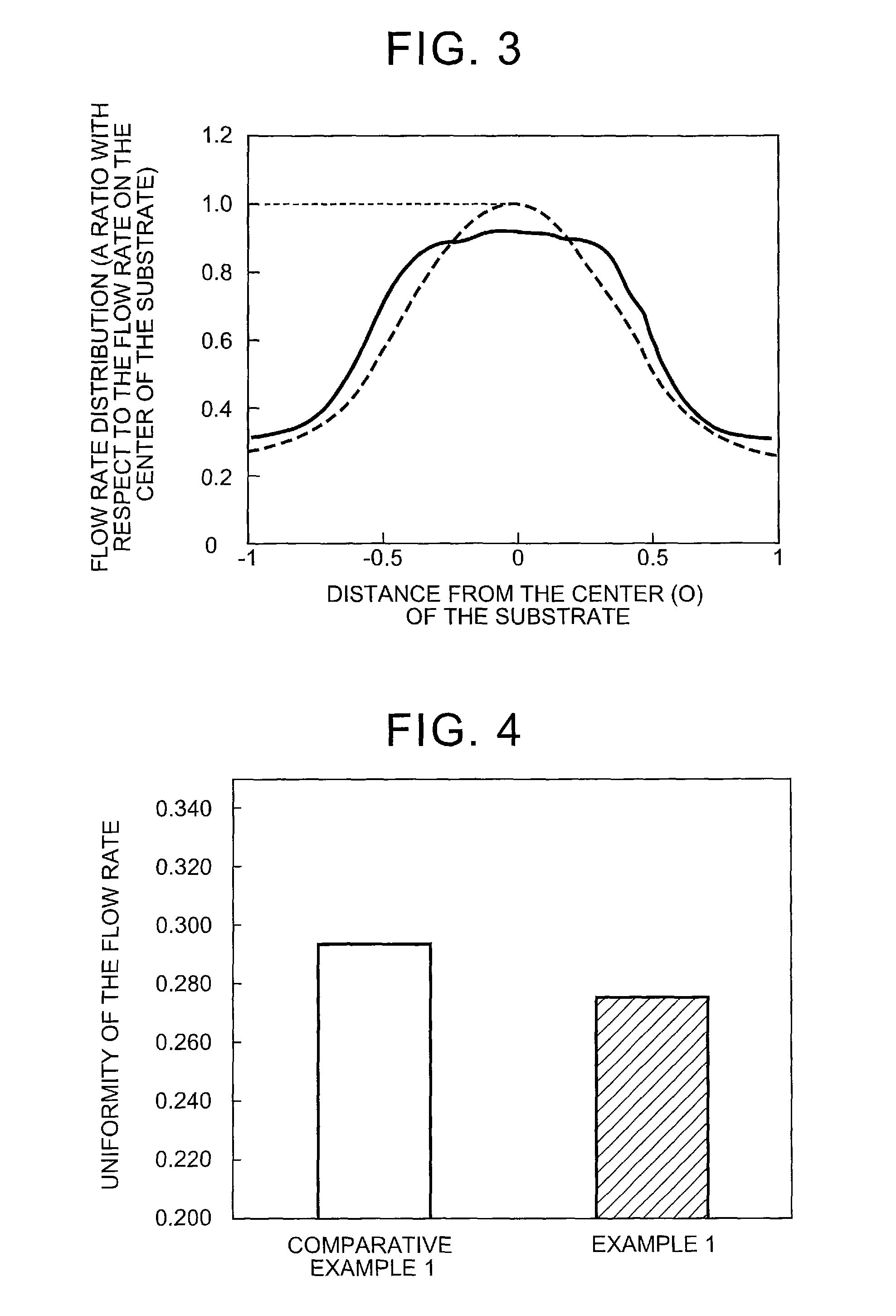
[0055]A honeycomb structured substrate made of cordierite is manufactured by press forming, and the cell densities in the center area and the surrounding area are different. The sizes of the honeycomb structure are as follows: a diameter φ of a circular cross section perpendicular to the flow direction of the exhaust gas is 103 mm, a length of a longitudinal direction is 105 mm, a cell density of the surrounding area with low cell density is 300 cpsi (52 per cm2), a cell density of the center area with high cell density is 600 cpsi (93 per cm2), and lattice shapes of the cells are all quadrilateral. In addition, the support constituting the catalyst layer is Al2O3—CeO2—ZrO2 composite oxide (ACZ material) supported with 0.3 g / L of Pt and 0.1 g / L of Rh as noble metal catalyst


PUM

PropertyMeasurementUnit
lengthaaaaaaaaaa
lengthaaaaaaaaaa
temperatureaaaaaaaaaa

Abstract

A catalytic converter including: a cell structured first substrate; and a cell structured second substrate provided at a downstream side of the first substrate. The first substrate has a uniform cell density. The second substrate includes a center area with a first cell density and a surrounding area with a second cell density that is lower than the first cell density. The first substrate and the second substrate are mounted in tandem.

Description

INCORPORATION BY REFERENCE[0001]The disclosure of Japanese Patent Application. No. 2013-231291 filed on Nov. 7, 2013 including the specification, drawings and abstract is incorporated herein by reference in its entirety.BACKGROUND OF THE INVENTION[0002]1. Field of the Invention[0003]The present disclosure relates to a catalytic converter which is accommodated and fixed in a pipe which is consisted of an exhaust system of exhaust gas.[0004]2. Description of Related Art[0005]In various industries, large effect has been made world widely to reduce the environmental influence load, especially in the automobile industry, not only the gasoline engine automobiles with excellent fuel efficiency, but also the popularization of so-called eco-cars such as hybrid automobiles and electric automobiles and the improvement of their performances are developing every day. Besides the development of such eco-cars, research about the exhaust gas purification catalyst for purifying the exhaust gas exhau...

Claims


Application Information

Patent Timeline
Patent Type & Authority Patents(United States)
IPC IPC(8): B01D53/94B01J23/63F01N13/00F01N3/28B01J35/00B01J35/04B01J35/10
CPCB01J35/0006B01D53/9454B01J23/63B01J35/04F01N3/28F01N3/2803F01N3/2828F01N13/0097B01D53/9477B01D2255/1021B01D2255/1025B01D2255/407B01J35/10F01N2330/48Y02T10/22Y02T10/12
Inventor AOKI, YUKISUZUKI, HIROMASAMATSUBARA, HIROYUKIHAYASHI, NAOHIRO
Owner TOYOTA JIDOSHA KK
Why Eureka
Try Eureka