
A kind of aircraft and its aircraft control method

A technology of the aircraft and the control part, which is applied in the direction of wing adjustment, etc., can solve the problems of reduced aileron efficiency, lower aileron, large torsional deformation of the wing, etc., and achieve the effect of avoiding aileron failure

Active Publication Date: 2021-03-30
INST OF HIGH SPEED AERODYNAMICS OF CHINA AERODYNAMICS RES & DEV CENT
View PDF2 Cites 0 Cited by
  • Summary
  • Abstract
  • Description
  • Claims
  • Application Information

AI Technical Summary

Problems solved by technology

[0006] The reason why the efficiency of conventional ailerons is reduced or reversed is that assuming that the ailerons deflect downward, an upward additional lift force and aerodynamic moment will be generated at the aileron aerodynamic center, and they will form a torque on the rigid center of the wing surface, making the wing surface A negative twist angle is generated, which causes the wing surface to generate negative additional lift, thereby reducing the effect of the aileron on increasing the lift, thus reducing the efficiency of the aileron or even counteracting it
Compared with the straight wing, the chord distance between the aileron and the wing root of the swept wing is relatively farther, so the torsional deformation of the wing caused by the aileron control moment is greater, and the aileron failure phenomenon is more serious

Method used


Image

  • A kind of aircraft and its aircraft control method
  • A kind of aircraft and its aircraft control method
  • A kind of aircraft and its aircraft control method

Examples


Embodiment 1

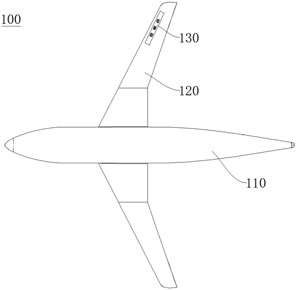
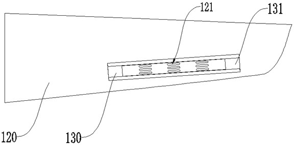
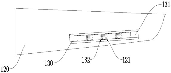
[0053] refer to figure 1 , the present embodiment provides an aircraft 100, including a fuselage 110 and wings 120, a control part 130 is arranged on one of the wings 120 near the tip of the wing, and the longitudinal center line of the control part 130 is in line with the longitudinal pressure of the wing 120. The center lines coincide, and the control unit 130 includes an aircraft rollover restraining device. In this embodiment, the number of wings 120 is two, so the number of control units 130 is also two, that is, they are arranged on both sides of the wings 120 with the fuselage 110 as the axis of symmetry.

[0054] In this embodiment, the longitudinal center of pressure of the control part 130 coincides with the longitudinal center of pressure of the wing 120. Through such a layout setting, in order to increase the rolling moment arm generated by the control surface, the longitudinal center of pressure of the control part The line coincides with the longitudinal center ...

Embodiment 2

[0068] The difference between this embodiment and Embodiment 1 lies in the driving assembly 133 a , and the driving assembly 133 b provided in this embodiment includes a spring 1333 and a firing mechanism 1334 .

[0069] In this embodiment, a spring 1333 and a firing mechanism 1334 are included, one end of the spring 1333 is fixed, the firing mechanism 1334 and the spring 1333 are installed at the same end, the slider 131 is connected to the other end of the spring 1333, and after the slider 131 compresses the spring 1333 Link to firing mechanism 1334 . In this embodiment, the firing mechanism 1334 is used to change the state of the slider 131 , that is, strike the slider 131 to make the slider 131 move in a certain direction.

[0070] In this embodiment, in order to achieve the limitation of the fixed position of the slider 131, a first limit block 134 and a second limit block 135 are provided, the first limit block 134 is arranged close to the spring 1333, and the second lim...


PUM


Abstract

The invention relates to the field of aircraft manufacturing, in particular to an aircraft and an aircraft control method thereof. The aircraft comprises a fuselage body and wings which are symmetrically arranged, a control part is arranged at the position, close to a wing tip, of any wing, each control part is used for controlling rolling motion of the corresponding wing, each control part comprises a rolling restraining device, each rolling restraining device comprises a shell and a sliding block, and the sliding blocks are movably arranged in the shells. The aircraft further comprises a driving assembly and a control assembly. The driving assembly is arranged in the shell and drives the sliding blocks to move in the shells. The control assembly is used for controlling the driving assembly to work, the sliding blocks and the shells are correspondingly provided with a plurality of open holes respectively, and the open holes of the sliding blocks and the open holes of the shells are selectively communicated along with the movement of the sliding blocks. According to the aircraft, the original aerodynamic configuration and the overall structure of the wings are not damaged, the occurrence of tumbling in the flight process is effectively improved, and the stability and the flight quality of the aircraft are not influenced.

Description

technical field [0001] The invention relates to the field of aircraft manufacturing, in particular to an aircraft and an aircraft control method thereof. Background technique [0002] The problem of static aeroelasticity of aircraft, also known as the problem of aeroelastic statics, belongs to the research category of aeroelasticity. For aircraft, the static aeroelasticity problem studies the deformation of the aircraft under aerodynamic loads and the stability characteristics of the static deformation generated by aerodynamic forces, and considers that force and motion are independent of time. Static aeroelastic deformation has a non-negligible impact on the aerodynamic performance of the aircraft, such as load distribution, control efficiency, trim characteristics, static and dynamic stability, and the safety, comfort, and economy of the aircraft under steady flight conditions. [0003] The structural deformation caused by the static aeroelastic effect of the wing will ha...

Claims


Application Information

Patent Timeline
Patent Type & Authority Patents(China)
IPC IPC(8): B64C3/38
CPCB64C3/38
Inventor 郭洪涛吕彬彬刘大伟李阳叶林余立张昌荣查俊郭鹏
Owner INST OF HIGH SPEED AERODYNAMICS OF CHINA AERODYNAMICS RES & DEV CENT
Learn More