
Semi-active rotor type reentry return device

A return device and semi-active technology, which is applied to the landing device of aerospace vehicles, the system of spacecraft returning to the earth's atmosphere, etc., can solve the problems of large mass of thermal protection system, limit the mass scale of reentry vehicles, etc., and achieve aerodynamic deceleration Effect

Active Publication Date: 2020-12-25
SHANGHAI AEROSPACE SYST ENG INST
View PDF15 Cites 0 Cited by
  • Summary
  • Abstract
  • Description
  • Claims
  • Application Information

AI Technical Summary

Problems solved by technology

In this type of scheme, due to the serious influence of aerodynamic heating, the performance requirements for the surface thermal protection material of the aircraft are extremely high, and the mass of the thermal protection system is relatively large, which greatly limits the mass scale of the reentry vehicle

Method used


Image

  • Semi-active rotor type reentry return device
  • Semi-active rotor type reentry return device
  • Semi-active rotor type reentry return device

Examples


Embodiment Construction

[0041] In order to make the object, technical solution and advantages of the present invention clearer, the embodiments disclosed in the present invention will be further described in detail below in conjunction with the accompanying drawings.

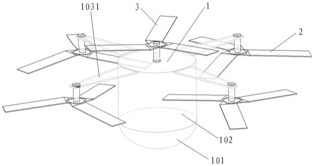
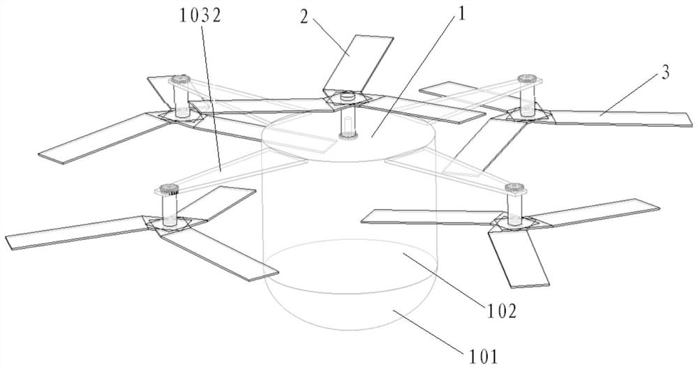
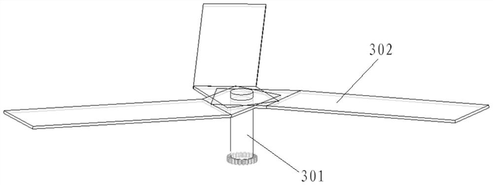
[0042] In this embodiment, the semi-active rotor type reentry and return device includes: an aircraft body 1 , N driving rotor devices 2 , M rotating rotor devices 3 and a transmission device 4 . Wherein, N and M are not less than 1, and specific values ​​may be determined according to actual conditions.

[0043] Such as figure 1 , the driving rotor device 2 can be evenly distributed in the circumferential direction of the aircraft body 1, and the rotating rotor device 3 can be evenly distributed in the circumferential direction of the aircraft body 1. Such as figure 2 , the driving rotor device 2 can also be arranged along the axial direction of the aircraft body 1, and the rotating rotor device 3 can also be evenly distributed in ...


PUM


Abstract

The invention discloses a semi-active rotor type reentry return device, comprising an aircraft body, N drive rotor devices, M rotating rotor devices and a transmission device, wherein the drive rotordevices are evenly distributed in the circumferential direction of the aircraft body and / or arranged in the axial direction of the aircraft body; the rotary rotor devices are uniformly distributed inthe circumferential direction of the aircraft body and / or are arranged in the axial direction of the aircraft body; and force transmission is carried out between the drive rotor devices and the rotaryrotor devices through a transmission device. High-speed aerodynamic characteristics of the aircraft in the reentry process are utilized, power is generated by the drive rotor devices, is converted bythe transmission device to push the rotary rotor devices to rotate, such that lift force hindering descending of the aircraft is generated, and therefore the reentry speed of the aircraft is reduced;and a semi-active deceleration mode is adopted, so that pneumatic deceleration of the aircraft in the reentry process can be realized more effectively.

Description

technical field [0001] The invention belongs to the technical field of aircraft reentry and return, and in particular relates to a semi-active rotor type reentry return device. Background technique [0002] With the development of my country's space technology, the demand for reentry and return of aircraft is becoming more and more urgent. When the aircraft re-enters and returns from space orbit, the re-entry speed is relatively high, which often produces a large aerodynamic heating. At present, for the reentry and return of the aircraft, two technologies are mainly used: lift body type aerodynamic return and parachute type aerodynamic return. The lift body reentry return is represented by the space shuttle. The reentry vehicle adopts the winged mode. Through the horizontal flight method, the wings of the aircraft are used to generate lift, which prolongs the reentry journey of the aircraft, thereby reducing the aerodynamic heat of the entire reentry process and reducing T...

Claims


Application Information

Patent Timeline
Patent Type & Authority Applications(China)
IPC IPC(8): B64G1/62
CPCB64G1/62
Inventor 潘雷韩艳李志刚马建颍李广兴陈超
Owner SHANGHAI AEROSPACE SYST ENG INST
Learn More