Novel combined compression type packer rubber sleeve

A combined compression and packer technology, applied in sealing/isolation, wellbore/well components, earthwork drilling and production, etc., can solve problems such as destruction, scrapping of oil and gas wells, and economic losses

Pending Publication Date: 2020-12-25
TIANJIN UNIV OF SCI & TECH
View PDF0 Cites 0 Cited by
  • Summary
  • Abstract
  • Description
  • Claims
  • Application Information

AI Technical Summary

Problems solved by technology

[0002] With the development of the petroleum industry, the fracturing packer as a stimulation tool for oil wells has been continuously improved and improved. As the core component of the fracturing packer, the rubber cartridge, its sealing failure will lead to early scrapping of oil and gas wells, resulting in huge economic losses. loss
Barrel packer rubber barrels widely used at present have a simple structure, but their sealing effect is poor under high temperature and high pressure, and they are prone to "shoulder" damage
In order to improve the pressure bearing capacity of the rubber cartridge, some rubber cartridges are designed with a metal anti-shoulder structure on the shoulder, but these metal anti-shoulder structures are not easy to recover due to their deformation when unsealing, and it is easy to cause difficulty in unsealing; two or three glue The combined structure of the cartridge can improve the sealing effect of the rubber cartridge, but increases the axial length of the packer

Method used


Image

  • Novel combined compression type packer rubber sleeve

Examples


Embodiment Construction

[0018] The implementation of the present invention is further described in conjunction with the accompanying drawings.

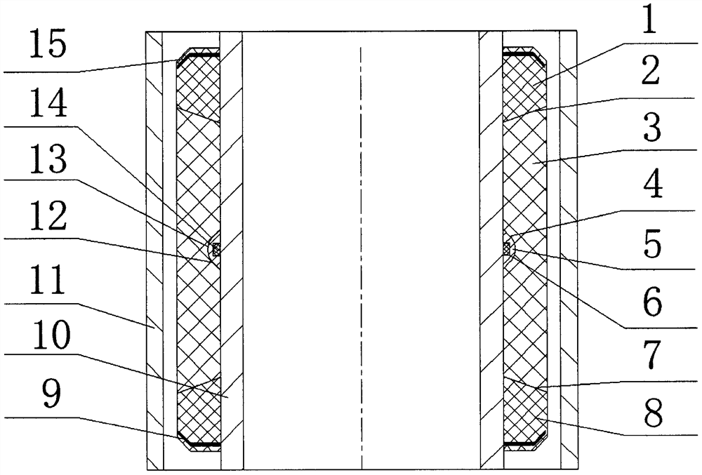
[0019] The present invention provides a new type of combined compression packer rubber sleeve, which includes an upper rubber sleeve 1, a middle rubber sleeve 3 and a lower rubber sleeve 8 between a central pipe 10 and a casing 11, and is characterized in that: the middle rubber sleeve The tube 3 is a "trapezoidal" section with a narrow inside and a wide outside. The upper rubber tube 1 and the lower rubber tube 8 are symmetrically set on the upper and lower ends of the middle rubber tube 3. The upper rubber tube 1 and the lower rubber tube 8 are in contact with the middle rubber tube 3. The upper and lower wedge-shaped slopes 2 and 7 are consistent with the shape of both sides of the rubber tube, and the end of the rubber tube is a plane. The shoulders of the upper rubber cylinder 1 and the lower rubber cylinder 8 are coated and vulcanized with upper and lo...


PUM


Abstract

The invention provides a novel combined compression type packer rubber sleeve. The novel combined compression type packer rubber sleeve comprises an upper rubber sleeve, a middle rubber sleeve and a lower rubber sleeve, all of which are arranged between a central pipe and a casing pipe. The middle rubber sleeve is a trapezoidal section with the interior narrower than the exterior, the upper end and the lower end of the middle rubber sleeve are symmetrically sleeved with the upper rubber sleeve and the lower rubber sleeve, wedge-shaped slope structures consistent with the two sides of the rubber sleeve in shape are arranged at the contact positions of the upper rubber sleeve and lower rubber sleeve with the middle rubber sleeve, and the ends away from the rubber sleeve are planes. Metal elastic rings are wrapped and vulcanized in the shoulder portions of the upper rubber sleeve and the lower rubber sleeve, the metal elastic rings are of dish-shaped structures, and dish openings face inwards. A special-shaped annular groove is formed in the middle position of the inner side of the middle rubber sleeve and is formed by combining a trapezoid section and a semicircular section, a metalsupporting piece is arranged in the special-shaped annular groove, the section shape of the metal supporting piece is consistent with that of the special-shaped annular groove, a rectangular groove isformed in the supporting piece, and an O-shaped sealing ring is arranged in the rectangular groove in a sleeved manner. The novel combined compression type packer rubber sleeve is compact in structure, scientific and reasonable in design and good in sealing effect, unsealing is easy, and the sealing reliability of the rubber sleeve under high-temperature and high-pressure working conditions can be improved.

Description

technical field [0001] The invention relates to a compression packer for underground high-pressure fracturing in oil production wells, in particular to a novel combined compression packer rubber cartridge. Background technique [0002] With the development of the petroleum industry, the fracturing packer as a stimulation tool for oil wells has been continuously improved and improved. As the core component of the fracturing packer, the rubber cartridge, its sealing failure will lead to early scrapping of oil and gas wells, resulting in huge economic losses. loss. The barrel-shaped packer rubber barrel widely used at present has a simple structure, but its sealing effect is poor under high temperature and high pressure, and it is prone to "shoulder" damage. In order to improve the pressure bearing capacity of the rubber cartridge, some rubber cartridges are designed with a metal anti-shoulder structure on the shoulder, but these metal anti-shoulder structures are not easy to ...

Claims


Application Information

Patent Timeline
Patent Type & Authority Applications(China)
IPC IPC(8): E21B33/127
CPCE21B33/1277
Inventor 张付英董城城水浩澈
Owner TIANJIN UNIV OF SCI & TECH
Why Eureka
Try Eureka