Connecting structure, plate connecting structure and bathroom cabinet

A technology of connecting structures and connecting parts, applied in the field of bathroom cabinets, can solve the problems of time-consuming and laborious operation requirements, cumbersome disassembly and assembly, etc., and achieve the effect of improving the effect of stopping back.

Pending Publication Date: 2020-12-25
JOMOO KITCHEN & BATHROOM
View PDF0 Cites 0 Cited by
  • Summary
  • Abstract
  • Description
  • Claims
  • Application Information

AI Technical Summary

Problems solved by technology

[0002] In existing cabinets (such as bathroom cabinets), the connection between the panels is usually fixed by using three-in-one eccentric connectors. In order to improve the connection strength, it is usually necessary to install multiple three-in-one joints One eccentric connector, when disassembling, it is necessary to use tools to disassemble or assemble all three-in-one eccentric connectors, which is cumbersome, time-consuming and labor-intensive, and requires high operation

Method used


Image

  • Connecting structure, plate connecting structure and bathroom cabinet
  • Connecting structure, plate connecting structure and bathroom cabinet
  • Connecting structure, plate connecting structure and bathroom cabinet

Examples


Embodiment 2

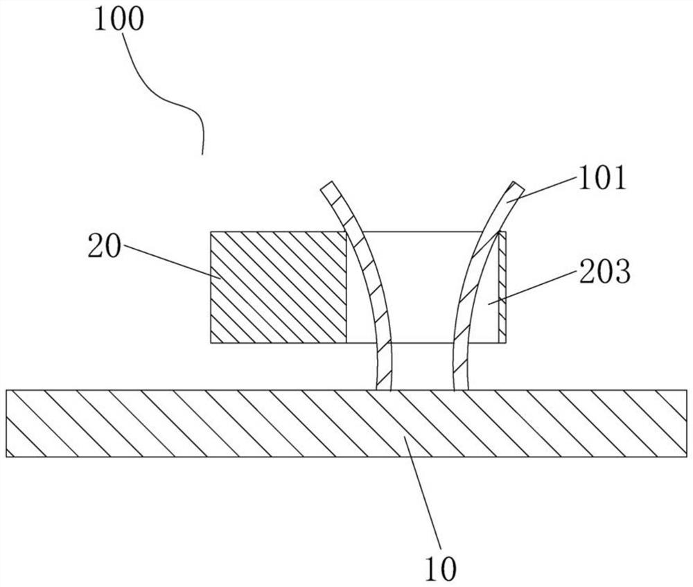
[0066] see figure 2 , figure 2 Shown is a schematic structural diagram of the connection structure 100 provided by the embodiment of the present invention.

[0067] Such as figure 2 As shown, the difference between the connection structure 100 provided by the embodiment of the present invention and the first embodiment of the connection structure 100 lies in the setting of the channel structure. Specifically, a third channel 203 is provided on the second object 20, and the third channel 203 constitutes a channel structure, which is composed of a square hole, and the two opposite side walls in the square hole are respectively used for the two elastic arms 101 For abutment, the size of the side of the square hole where the elastic arm 101 abuts is matched with the width of the elastic arm 101 .

[0068] In this embodiment, when the first object 10 and the second object 20 are connected in place, the free ends of the two elastic arms 101 pass through the third passage 203, ...

Embodiment 3

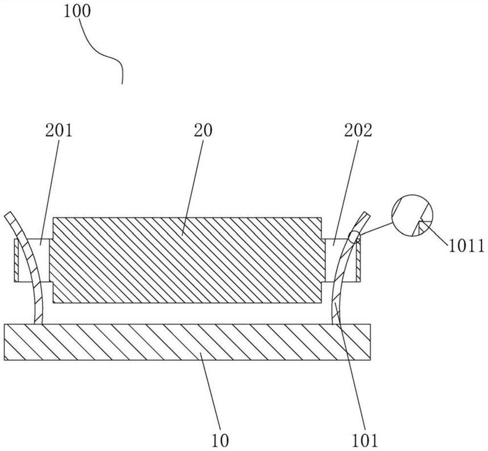
[0075] see image 3 , image 3 Shown is a schematic structural diagram of the connection structure 100 provided by the embodiment of the present invention.

[0076] Such as image 3 As shown, the difference between the connection structure 100 provided by the embodiment of the present invention and the first embodiment of the connection structure 100 lies in that the inclination directions of the two elastic arms 101 and the positions of the locking protrusions 1011 are different. Specifically, in this embodiment, the first object 10 is provided with two elastic arms 101 extending obliquely along the first direction, and the free ends of the two elastic arms 101 face each other in a second direction perpendicular to the first direction; The first side of each elastic arm 101 is provided with a locking protrusion 1011; the first side is specifically the side of the two elastic arms 101 close to each other.

[0077] When the first object 10 and the second object 20 are connec...


PUM


Abstract

The invention discloses a connecting structure, a plate connecting structure and a bathroom cabinet. The connecting structure is used for connecting a first object to a second object in the first direction. The first object is provided with two elastic arms which obliquely extend in the first direction. The first sides of the two elastic arms are provided with clamping protrusions, and the free ends of the two elastic arms are back onto each other or opposite in the second direction perpendicular to the first direction. The second object is provided with a through channel structure. When the first object and the second object are connected in place, the free ends of the two elastic arms penetrate through the channel structure, the elastic arms are matched with the channel structure in thethird direction perpendicular to the first direction and the second direction, the two clamping protrusions abut against the end, close to the free ends of the elastic arms, of the channel structure in a retaining mode, and the first object is fixed relative to the second object. The plate connecting structure and the bathroom cabinet adopt the connecting structure. According to the connecting structure, the plate connecting structure and the bathroom cabinet, rapid disassembly and assembly of a plate can be achieved, and reduction of the labor cost during disassembly and assembly is facilitated.

Description

technical field [0001] The invention relates to the technical field of bathroom cabinets, in particular to a connection structure, a board connection structure and a bathroom cabinet. Background technique [0002] In existing cabinets (such as bathroom cabinets), the connection between the panels is usually fixed with a three-in-one eccentric connector. When disassembling an eccentric connector, tools are required to disassemble or assemble all three-in-one eccentric connectors, which is cumbersome, time-consuming and labor-intensive, and requires high operating requirements. Contents of the invention [0003] The purpose of the present invention is to overcome at least one defect or problem existing in the background technology, and provide a connection structure, a panel connection structure, and a bathroom cabinet, which can realize quick disassembly and assembly of panels, and are beneficial to reduce the time required for disassembly and assembly. Consumed labor cost...

Claims


Application Information

Patent Timeline
IPC IPC(8): F16B2/22F16B5/06A47K1/02
CPCA47K1/02F16B2/22F16B5/0614
Inventor 林孝发林孝山石岩林波泉任晓辉
Owner JOMOO KITCHEN & BATHROOM
Why Eureka
Try Eureka