Guide rail mechanism for restraining rotation of brake pad supports and clamp braking device provided with guide rail mechanism

A technology of brake pad holders and guide rails, which is applied in the direction of axially joined brake components, brake types, brake components, etc., can solve the problems of unfavorable brake pad holders with extra torque, mutual incompatibility, and influence on anti-deflection effects, etc. , to achieve the effects of improving safety and reliability, avoiding abnormal eccentric wear, and reducing maintenance and repair costs

Pending Publication Date: 2020-12-25
CRRC CHANGZHOU TECH MARK IND CO LTD +1
View PDF0 Cites 0 Cited by
  • Summary
  • Abstract
  • Description
  • Claims
  • Application Information

AI Technical Summary

Problems solved by technology

[0004] However, practice has shown that in this existing rail-type anti-eccentric wear mechanism, since the rail constraining the swing degree of freedom of the brake pad holder is located on the other side of the constrained brake pad holder, it is necessary to realize the connection between the rail and the constrained brake pad holder. , it will inevitably lead to the meandering of the guide rail connecting rods and the two guide rail connecting rods must be arranged in a cross
The anti-eccentric wear mechanism of this "reverse restraint" brake pad holder makes the design and manufacture of the guide rail connecting rod and the track curve of the guide rail very complicated and cumbersome, and takes up a relatively large space, and because the two guide rail connecting rods must be "X" Shaped cross arrangement makes them incompatible with each other. In addition, it is necessary to ensure that there is enough clearance between the two connecting rods after assembly to avoid interference during vehicle braking and vehicle operation, which makes assembly difficult.
Moreover, the applicant found that the direction of the restraining force exerted by the guide rail on the end of the connecting rod obviously deviates from the associated brake holder, so when the brake holder is constrained to rotate, it will be unfavorable to maintain the brake holder. Parallel additional torque; and the long and narrow guide rail connecting rod is easily deformed by external force, which further affects the anti-deflection function

Method used


Image

  • Guide rail mechanism for restraining rotation of brake pad supports and clamp braking device provided with guide rail mechanism
  • Guide rail mechanism for restraining rotation of brake pad supports and clamp braking device provided with guide rail mechanism
  • Guide rail mechanism for restraining rotation of brake pad supports and clamp braking device provided with guide rail mechanism

Examples


Embodiment 1

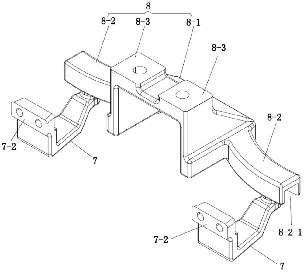
[0049]The guide rail mechanism for restricting the rotation of the brake pad holder in this embodiment is as followsfigure 1 As shown, the guide rail seat 8 is included. The mounting part of the guide rail seat 8 is composed of a support body 8-1 with two spaced upper mounting platforms 8-3 at one end. The upper mounting platform 8-3 is used for connecting the caliper brake device The bottom of the clamp body 1 is connected. The support may be a solid structure, but preferably a hollow structure that helps reduce weight. The bottom edges of the vertical extending surfaces outside the two upper installation platforms 8-3 of the installation part respectively extend out of the guide rail 8-2 through reinforcing ribs. Preferably, the inner end of the guide rail 8-2 is arranged at the rear end of the bottom edge of the vertical extension surface, which is more conducive to the track design of the guide groove; the guide rail 8-2 has an end connected to the connecting rod 7 (extending fr...

Embodiment 2

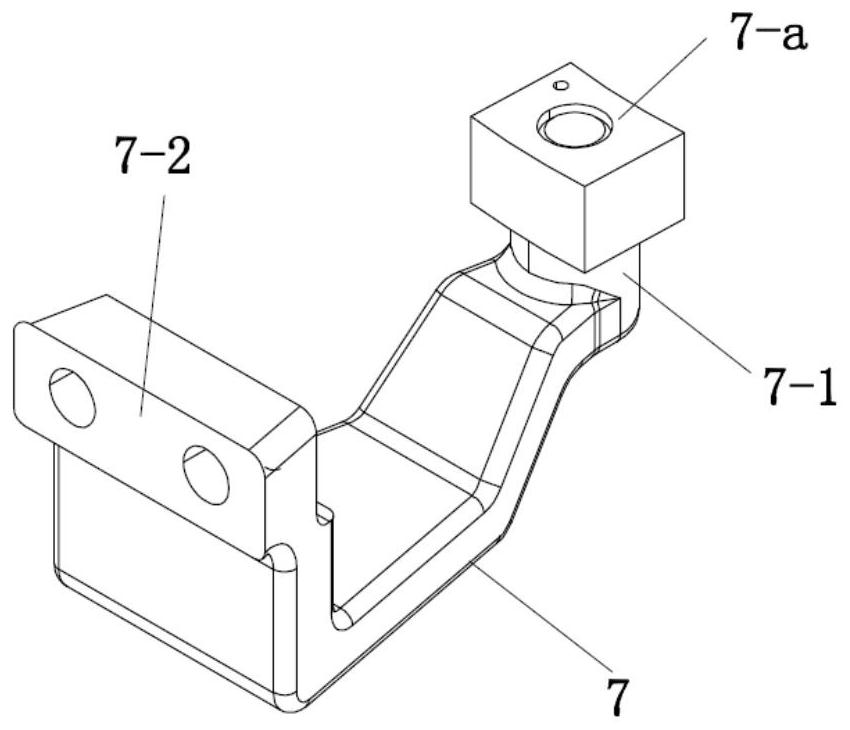
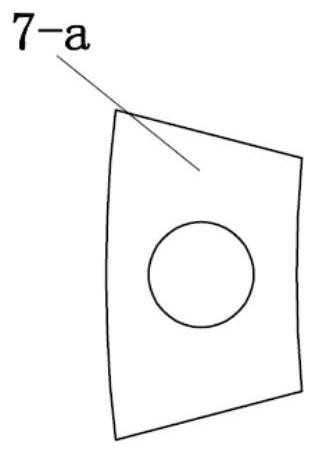
[0064]The guide rail mechanism for restricting the rotation of the brake pad holder in this embodiment is as followsFigure 8 withPicture 9 As shown, the difference from the first embodiment is that the guide rail 8-2 has a front opening guide groove 8-2-1 which forms a cam pair with one end of the connecting rod 7; the connecting rod 7 is in the shape of a plate, and one end is directly along the length direction. A cylindrical connecting column 7-1 is extended to form a cam pair directly with the front opening guide groove 8-2-1 of the guide rail 8-2; the other end extends away from the connecting column 7-1 in the length direction and is directly formed The front installation platform 7-2, the front installation platform 7-2 is fixedly connected with the brake pad holder on the same side. Therefore, the structure is simpler. Since the front mounting platform 7-2 is used to connect with the brake pad, the width of the other end of the connecting rod 7 is greater than the width of t...


PUM


Abstract

The invention relates to a guide rail mechanism for restraining rotation of brake pad supports and a clamp braking device provided with the guide rail mechanism, and belongs to the technical field ofvehicle braking. The guide rail mechanism comprises a guide rail seat and connecting rods, two sides of a mounting part of the guide rail seat extend to form guide rails correspondingly, the guide rails are provided with guide grooves forming a cam pair with one ends of the connecting rods, one ends of the connecting rods are in sliding fit with the guide rail guide grooves on the same sides, theother ends of the connecting rods are fixedly connected with the brake pad supports on the same sides hinged to one ends of levers, the track of each guide groove is an arc track taking the other acute angle vertex of a parallelogram which takes the corresponding lever fulcrum as one of obtuse angle vertexes and takes the connecting line between the corresponding lever fulcrum and the center of avertical pin of the brake pad support on the same side as one side as the circle center and taking the distance between the corresponding lever fulcrum and the center of the vertical pin of the brakepad support on the same side as the radius. According to the guide rail mechanism and the clamp braking device, the translation process that the connecting rods drive the brake pad supports is easy torealize and control, no extra torque is generated, no motion interference is generated, the rigidity is easy to ensure, and the eccentric wear of brake pads is more effectively avoided.

Description

Technical field[0001]The invention relates to a guide rail mechanism for restraining the rotation of a brake pad holder, and also relates to a caliper brake device equipped with the guide rail mechanism, belonging to the technical field of vehicle braking.Background technique[0002]The basic structure of the caliper brake device is that the two sides of the caliper body respectively hinge the middle of a lever, a brake cylinder is installed between one end of the two levers, and the other end is hinged with a brake pad holder through a vertical pin; fixed to the brake pad The brake pads on the support face the surface of the brake disc mounted on the wheel or axle. When the brake cylinder is extended, under the action of the lever, the brake pads on the two brake pad holders will simultaneously close to the brake disc surfaces installed on the wheels or axles to achieve braking. However, since the brake pad holder has no restriction on its degree of freedom to swing around the vertic...

Claims


Application Information

Patent Timeline
Patent Type & Authority Applications(China)
IPC IPC(8): F16D65/00
CPCF16D65/0006F16D65/005F16D65/0056F16D65/0068F16D65/0087
Inventor 韩红文朱君华曾梁彬鲍春光
Owner CRRC CHANGZHOU TECH MARK IND CO LTD
Why Eureka
Try Eureka