
Optical fiber time delay measurement method and device based on single optical frequency comb interference

A time-delay measurement and optical frequency comb technology, which is applied in the field of optical measurement, can solve the problems of easy change of slide position, difficult operation, and high equipment requirements, and achieve the effects of fast measurement speed, flexible control, and high flexibility

Active Publication Date: 2021-08-24
NANJING UNIV OF AERONAUTICS & ASTRONAUTICS
View PDF0 Cites 0 Cited by
  • Summary
  • Abstract
  • Description
  • Claims
  • Application Information

AI Technical Summary

Problems solved by technology

This type of measurement method needs to lock the two optical combs to avoid drift caused by environmental influences, the structure is complex and the cost is high, and it can only be applied to the absolute distance measurement of space light, and the measurement range is relatively small
The single optical comb also shows a good advantage in space ranging. The Korea Institute of Science and Technology (KAIST) uses a Sagnac interferometer structure combined with phase-locked feedback, and uses a mode-locked laser to generate an optical frequency comb signal to measure the microwave The time delay difference between the signal and the optical frequency comb signal has achieved sub-femtosecond delay measurement accuracy (Na Y, Jeon C-G, Ahn C, et al. Ultrafast, sub-nanometre-precision and multifunctional time-of-flight detection [J].Nature Photonics,2020,14(6):355-360.) Due to the periodicity of optical frequency comb signals and microwave signals, the measurement range of this type of measurement method is relatively small, only at the millimeter level
In addition, due to the adoption of a feedback mechanism, a glass slide and a Faraday rotating mirror need to be added to the Sagnac interference loop to achieve a π / 2 phase difference. The position of the slide is easy to change, and the calibration of the slide needs to be adjusted before measurement, which is difficult to operate; the interference ring The high-cost polarization-maintaining fiber must also be used in the path; in addition, in order to achieve stable measurement results, the solution also needs to use high-quality voltage-controlled oscillators and mode-locked lasers
In summary, the single-comb delay measurement system has a complex structure, high equipment requirements, difficult operation, and small measurement range. Currently, it can only be used for spatial light measurement, and is not suitable for delay measurement in optical fibers.

Method used


Image

  • Optical fiber time delay measurement method and device based on single optical frequency comb interference
  • Optical fiber time delay measurement method and device based on single optical frequency comb interference
  • Optical fiber time delay measurement method and device based on single optical frequency comb interference

Examples


Embodiment Construction

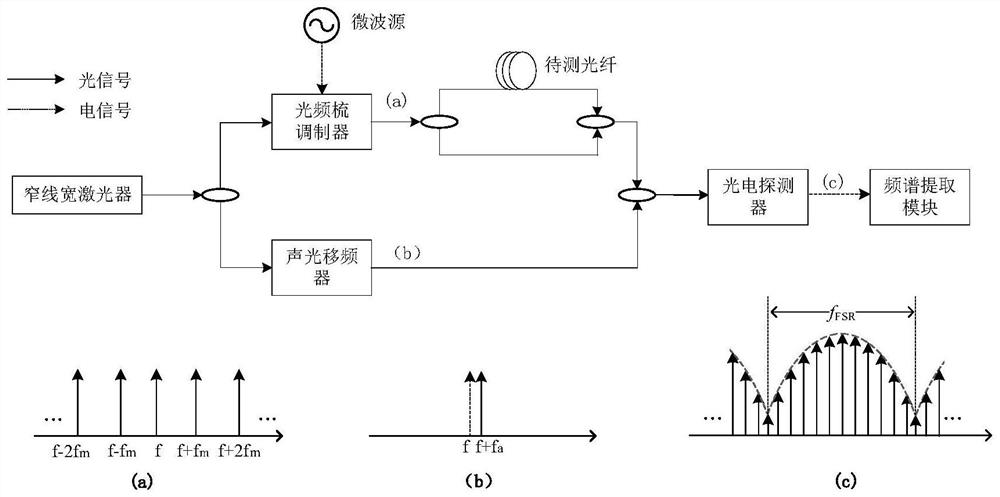
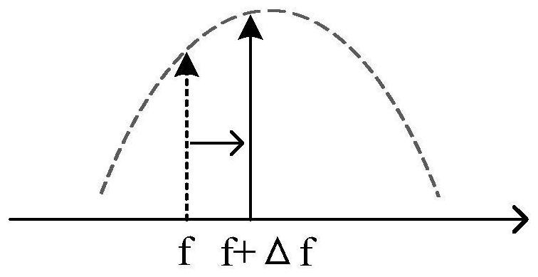
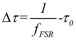
[0035]Aiming at the shortcomings of the existing technology, the solution of the present invention is to use the optical frequency comb signal as the input light source of the interferometer, and use the abundant frequency components in the optical frequency comb to replace the frequency sweep process in the traditional interferometer system, greatly improving the measurement speed; The signals entering the two arms of the interferometer come from the same optical frequency comb signal, which avoids the influence of the frequency drift of the optical frequency comb caused by the environment; at the same time, the spectral information of the interference signal is mapped from the optical domain to the electrical domain by using heterodyne reception In the above, the free spectrum range f of the interference signal is accurately obtained by using the high-precision spectrum measurement method in the relatively low-frequency electric domain FSR , and then solve the time delay of t...


PUM


Abstract

The invention discloses an optical fiber time delay measurement method based on single optical frequency comb interference, which divides the optical carrier output by a narrow linewidth laser into two paths, wherein one optical carrier is modulated into an optical frequency comb signal by an optical frequency comb modulator , sent to the interferometer connected to the optical fiber to be tested, and another optical carrier for frequency shift processing; after the frequency shifted optical carrier is coupled with the optical signal output by the interferometer, photoelectric detection is performed to obtain a microwave signal carrying time delay information ; Extract the spectrum information of the microwave signal, and then extract the free spectrum range of the interference spectrum, and calculate the time delay of the optical fiber to be tested according to the free spectrum range of the interference spectrum. The invention also discloses an optical fiber time delay measurement device based on single optical frequency comb interference. Compared with the prior art, the invention has the advantages of high measurement stability, fast measurement speed, simple structure and low implementation cost.

Description

technical field [0001] The invention relates to a method for measuring optical fiber time delay, which belongs to the technical field of optical measurement. Background technique [0002] Delay is a basic parameter in signal generation, transmission, control and processing. With the rapid development of optical fiber electronic information systems, the rapid and stable measurement and control of time delay in optical fiber links has become an optically controlled phased array, distributed The key to the research and application of high-performance information systems such as radar networks and optical fiber time-frequency transmission. [0003] There are three commonly used optical fiber delay measurement methods: pulse method, phase push method, and frequency-sweeping interferometry. The pulse method is also called the time-domain method. The time delay of the optical fiber to be tested is obtained by directly recording the time interval between the transmitted optical pul...

Claims


Application Information

Patent Timeline
Patent Type & Authority Patents(China)
IPC IPC(8): G01M11/00G01M11/02H04B10/079
CPCG01M11/02G01M11/331G01M11/333H04B10/0795
Inventor 王祥传刘熙潘时龙王立晗汤晓虎
Owner NANJING UNIV OF AERONAUTICS & ASTRONAUTICS
Learn More