Modal test method of large draught fan blade based on photography measurement technology

A technology of fan blades and photogrammetry, applied in measuring devices, measuring ultrasonic/sonic/infrasonic waves, instruments, etc., can solve the problem of high cost of a single scaled blade, inconvenient arrangement of camera LED light-emitting tubes, and inability to truly reflect the vibration state of the structural space, etc. problems, to achieve the effect of convenient operation, high precision and fast measurement speed

Active Publication Date: 2017-07-28
HUNAN UNIV OF SCI & TECH
View PDF14 Cites 35 Cited by
  • Summary
  • Abstract
  • Description
  • Claims
  • Application Information

AI Technical Summary

Problems solved by technology

This method has the problems of high cost of manufacturing a single scaled-scale blade, and the fact that it cannot be accurately scaled according to the real structure of a full-scale blade.
[0005] The existing non-contact vibration measurement method based on digital images in the prior art, such as patent application number 2013102249219, patent name: Measuring device and method for vibration of flexible cantilever beam based on machine vision, the measurement object is limited to simple cantilever beam structure , the installation of the camera and the layout of the LED light-emitting tube are inconvenient, and the simple acquisition of one-dimensional vibration signals by a single camera cannot truly reflect the spatial vibration state of the structure; the master's thesis "Research on On-orbit Vibration Measurement of Large Flexible Structures Based on Binocular Stereo Vision" , the actual research object is also simplified to a beam or plate-shaped simple structure, and there is no reasonable solution for the identification of structural modal parameters based on vibration signals

Method used


Image

  • Modal test method of large draught fan blade based on photography measurement technology
  • Modal test method of large draught fan blade based on photography measurement technology
  • Modal test method of large draught fan blade based on photography measurement technology

Examples


Embodiment Construction

[0047]In order to enable those skilled in the art to better understand the technical solution of the present invention, the present invention will be described in further detail below in conjunction with the accompanying drawings and specific embodiments. And the features in the embodiments can be combined with each other.

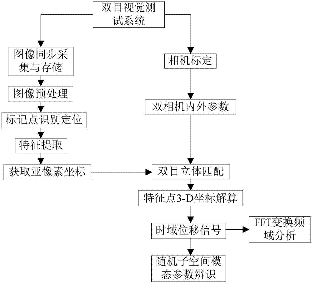
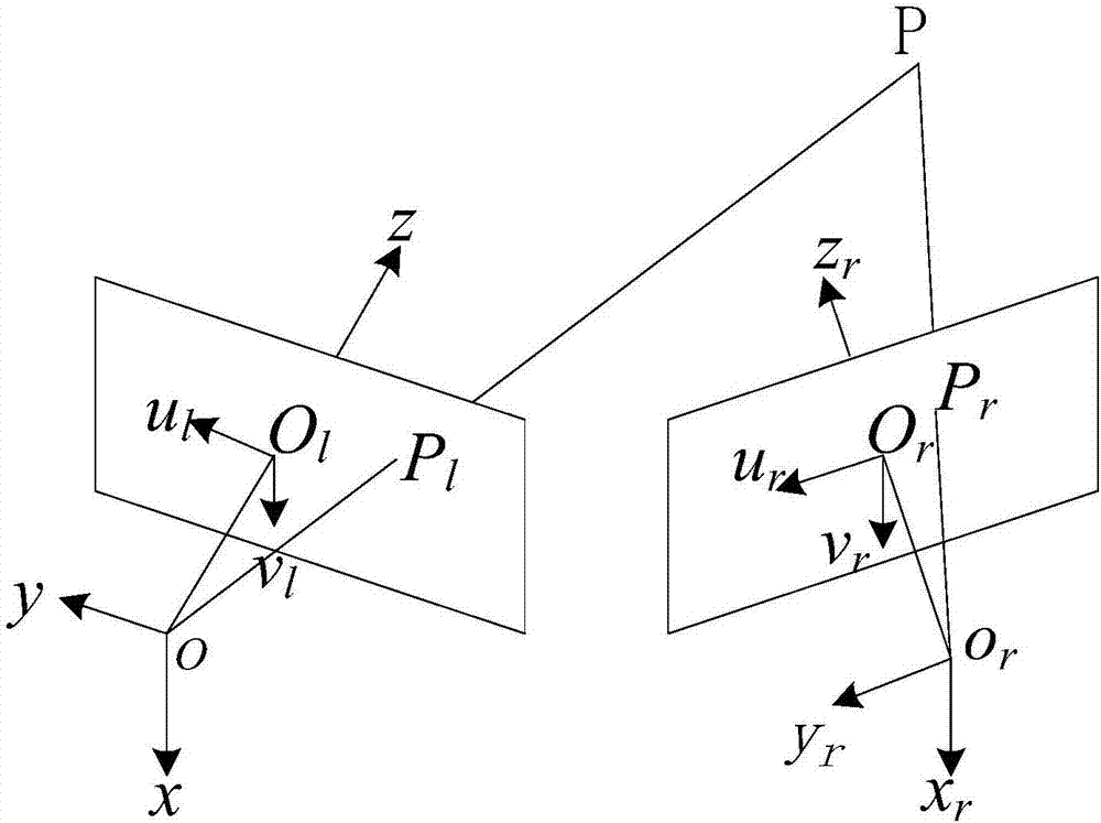
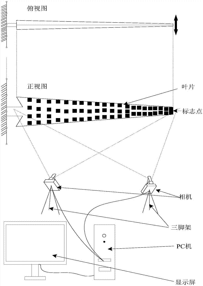
[0048] The core of the present invention is to provide a large-scale wind turbine blade modal test method based on photogrammetry technology, which adopts a pair of CMOS / CCD industrial cameras to synchronously shoot the surface image of the wind turbine blade under random excitation vibration, and identify and locate multiple The sub-pixel-level coordinates of the center of the marked point are extracted and the stereo matching of the two cameras is performed. The three-dimensional coordinates of each measuring point are calculated by three-dimensional reconstruction technology, and the displacement data is differentially processed to obtain the required vi...


PUM


Abstract

The invention discloses a modal test method of a large draught fan blade based on the photography measurement technology. The method comprises steps of using a pair of CMOS/CCD industrial cameras to carry out synchronous shooting on surface images of the draught fan blade under random excitation vibration; identifying and positioning multiple marking points in the images; extracting central sub-pixel level coordinates of the marking points and carrying out stereo matching of the double cameras; calculating three-dimensional coordinates of each measurement point through the three-dimensional reconstruction technology; carrying out micro-division processing on displacement data to obtain required vibration response (speed and accelerated speed) signals; through the Fourier transform, converting time domain signals into observation peak values in frequency domains to find corresponding modal frequencies; by combining analyzed frequency values, further using the stochastic subspace identification method (SSI) to precise calculate modal parameters of the blade; and acquiring the fixed frequency, the vibration mode and the damping ratio of the blade. According to the invention, by use of non-contact type multi-point synchronous vibration measurement, rapid high-precision model test on the draught fan blade can be achieved.

Description

technical field [0001] The invention belongs to the technical field of fan blade testing, and in particular relates to a modal testing method for large fan blades based on photogrammetry technology. Background technique [0002] Wind turbine blades are subjected to wind load during operation, which is easy to cause vibration. When the vibration frequency is close to or multiplied by the natural frequency of the blade, resonance will occur, which may cause fatigue cracks on the blade and reduce the working life. In severe cases, the blades break and the unit is damaged. Therefore, before the blade is installed and operated, it is necessary to perform a pre-factory performance test on the blade to ensure that the mode of each blade includes: the consistency of natural frequency, damping and mode shape, so that the working frequency band can avoid the natural frequency of the blade as much as possible, otherwise It will affect the stability of impeller operation. [0003] Exi...

Claims


Application Information

Patent Timeline
Patent Type & Authority Applications(China)
IPC IPC(8): G01H9/00
CPCG01H9/00
Inventor 王文韫陈安华李学军蒋勉沈意平丁佳乐
Owner HUNAN UNIV OF SCI & TECH
Why Eureka
Try Eureka