
A device and method for removing electromagnetic interference signals in the same frequency band

A technology of electromagnetic interference and the same frequency band, which is applied in the field of test signal processing devices, can solve problems such as electromagnetic interference, inability to use frequency band mixed signal processing, and inability to effectively shield low-frequency electromagnetic signals, so as to achieve the effect of ensuring authenticity and accuracy

Active Publication Date: 2021-11-09
浙江中裕通信技术有限公司
View PDF0 Cites 0 Cited by
  • Summary
  • Abstract
  • Description
  • Claims
  • Application Information

AI Technical Summary

Problems solved by technology

When using a magnetic sensor to measure attitude information, the sensor measurement information is extremely susceptible to electromagnetic interference generated by changing currents when other circuit modules are working, resulting in very large errors
Most of the circuit operating current changes are low-frequency and near-zero-frequency changes. Electromagnetic interference is also a low-frequency signal that is mixed with the frequency band of the magnetic signal containing the flight attitude information of the missile and sent to the sensor end. The existing test signal processing methods focus on different frequency bands. Or frequency point signal separation, separating interference signals from frequency domain filtering, but it cannot be used for processing mixed frequency band signals, and it is difficult to remove interference signals in later calibration
Blind signal separation technology has requirements on the number of sensors and the mixing method of signal sources, and has no good separation effect on mixed signals of the same frequency band mixed in from the sensing end of the same sensor
Moreover, traditional electromagnetic shielding technology cannot effectively shield low-frequency electromagnetic signals, and cannot achieve the purpose of removing interference by shielding other circuit modules

Method used


Image

  • A device and method for removing electromagnetic interference signals in the same frequency band
  • A device and method for removing electromagnetic interference signals in the same frequency band
  • A device and method for removing electromagnetic interference signals in the same frequency band

Examples


Embodiment Construction

[0042] A device and method for removing electromagnetic interference signals in the same frequency band according to the present invention will be further described in detail below in conjunction with the accompanying drawings.

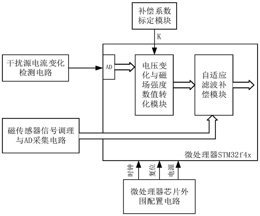
[0043] Such as figure 1 As shown, a device for removing electromagnetic interference signals in the same frequency band includes an interference source current change detection circuit module, a magnetic sensor signal conditioning and AD acquisition module, a microprocessor, a microprocessor peripheral configuration circuit module, and a compensation coefficient calibration module; The device includes AD acquisition interface, voltage change and magnetic field strength value conversion module, adaptive filter compensation module;

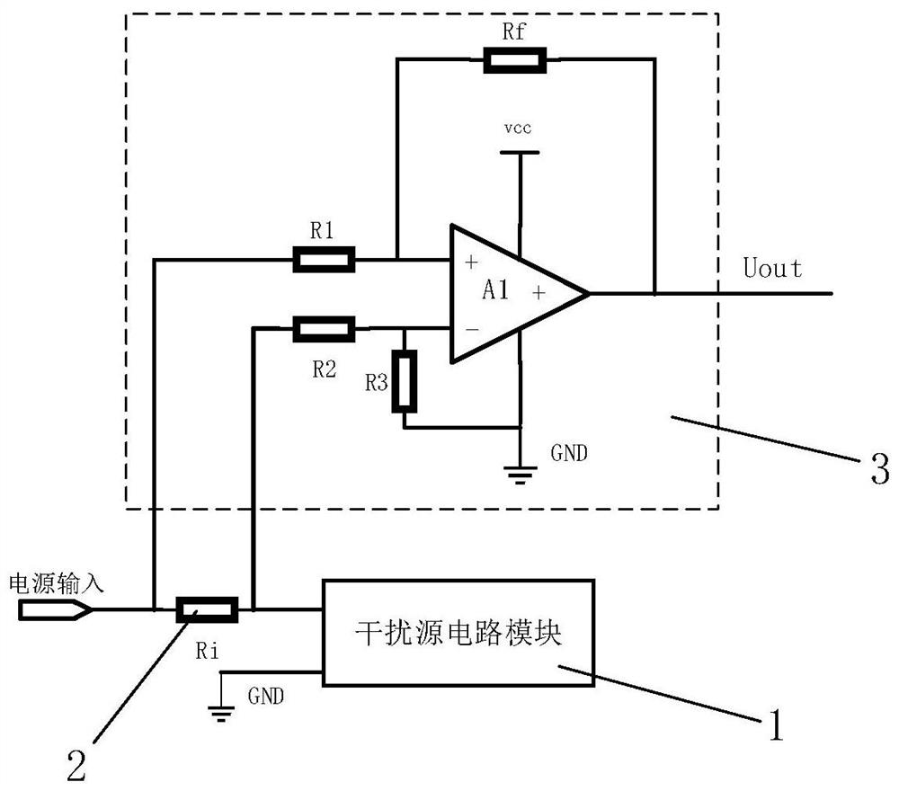
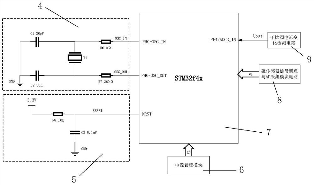
[0044] The microprocessor is used to run the algorithm of the voltage change and magnetic field strength value conversion module and the adaptive filter compensation module; the interference source current change detection ...


PUM


Abstract

The invention discloses a device and method for removing electromagnetic interference signals in the same frequency band. The device includes an interference source current change detection circuit module, a magnetic sensor signal conditioning and AD acquisition circuit module, a microprocessor, a microprocessor peripheral configuration circuit module, A voltage change and magnetic field strength value conversion module, an adaptive filter compensation module and a compensation coefficient calibration module; the method uses a compensation method and an adaptive filter algorithm to achieve the purpose of eliminating interference. The invention separates the useful magnetic signal and the interfering magnetic signal on the chip through an adaptive filtering algorithm, which effectively solves the problem that the signals cannot be effectively separated after the same-frequency signal is mixed into the sensor sensing end, and can realize the geomagnetic sensor in a strong electromagnetic interference environment. achieve higher test accuracy.

Description

technical field [0001] The invention relates to a test signal processing device and method, in particular to a device and method for removing electromagnetic interference signals in the same frequency band. Background technique [0002] Today's missile navigation, ballistic measurement and other projects mostly use miniaturized measurement systems with multi-sensor fusion. When using a magnetic sensor to measure attitude information, the sensor measurement information is extremely susceptible to electromagnetic interference generated by changing currents when other circuit modules are working, resulting in very large errors. Most of the circuit operating current changes are low-frequency and near-zero-frequency changes. Electromagnetic interference is also a low-frequency signal that is mixed with the frequency band of the magnetic signal containing the flight attitude information of the missile and sent to the sensor end. The existing test signal processing methods focus on...

Claims


Application Information

Patent Timeline
Patent Type & Authority Patents(China)
IPC IPC(8): G01R29/08G05B19/042
CPCG01R29/0871G01R29/0892G05B19/0428G05B2219/2612
Inventor 管雪元马训穷薄振华
Owner 浙江中裕通信技术有限公司
Learn More