
Method for dynamically modifying PCH PCIE root port where onboard VGA is located

A root port, onboard technology, applied in the computer field, can solve the problem that the onboard VGAPCHPCIE root port cannot be dynamically modified

Active Publication Date: 2020-12-25
SUZHOU LANGCHAO INTELLIGENT TECH CO LTD
View PDF1 Cites 1 Cited by
  • Summary
  • Abstract
  • Description
  • Claims
  • Application Information

AI Technical Summary

Problems solved by technology

[0007] The purpose of this application is to provide a method, device, equipment and readable storage medium for dynamically modifying the PCH PCIE root port where the onboard VGA is located, so as to solve the problem that the PCHPCIE where the onboard VGA is located cannot be dynamically modified in a set of BIOS codes at present. root port problem

Method used


Image

  • Method for dynamically modifying PCH PCIE root port where onboard VGA is located
  • Method for dynamically modifying PCH PCIE root port where onboard VGA is located
  • Method for dynamically modifying PCH PCIE root port where onboard VGA is located

Examples


Embodiment 1

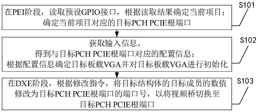
[0044] The following introduces a method embodiment one of a method for dynamically modifying the PCH PCIE root port where the onboard VGA is provided by the application, see figure 1 , embodiment one includes:

[0045] S101. In the PEI stage, read the preset GPIO interface, and determine the current project according to the reading result; determine the target PCH PCIE root port corresponding to the current project;

[0046] When designing the motherboard, reserve several GPIO interfaces. When the motherboard is powered on, it enters the PEI stage (Pre-EFINitialization, EFI pre-initialization stage), and determines the currently started project by reading these GPIO interfaces, and then determines the PCH PCIE root port used by the project.

[0047] Specifically, a project ID is set for each project of the current platform; at the PEI stage, the preset GPIO interface is read to obtain the reading result; the project whose project ID is the reading result is determined as the...

Embodiment 2

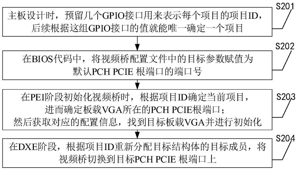
[0055] The following begins to introduce in detail the second embodiment of a method for dynamically modifying the PCH PCIE root port where the onboard VGA is located, see figure 2 , embodiment two specifically includes:

[0056] S201. When designing the motherboard, several GPIO interfaces are reserved to represent the project ID of each project, and a project can be uniquely determined later based on the values ​​of this group of GPIO interfaces.

[0057] Assuming that 8 GPIOs are reserved, when the value of this group of GPIO interfaces is 00000001, it indicates that the currently started project is project 1, and when the value of this group of GPIO interfaces is 00000010, it indicates that the currently started project is project 2.

[0058] S202. In the BIOS code, assign the target parameter in the video bridge configuration file to the port number of the default PCH PCIE root port.

[0059] There are many parameters in the video bridge configuration file, and the targ...


PUM


Abstract

The invention discloses a method, device and equipment for dynamically modifying a PCH PCIE root port where an onboard VGA is located and a readable storage medium, and the method comprises the steps:determining a current project at a PEI stage through reading a GPIO interface, and further determining a target PCH PCIE root port used by the project; and obtaining configuration information, and finding and initializing a target onboard VGA; due to the fact that the video bridge configuration file defined in the SDL file can be stored in the structural body of the temporary file during code compiling, the method modifies the numerical value of the target member of the structural body into the port number of the target PCH PCIE root port in the DXE stage, and therefore the video bridge is switched to the target PCH PCIE root port. Therefore, according to the method, the PCH PCIE root port where the onboard VGA is located can be dynamically modified, the onboard VGA can be normally displayed without changing BIOS codes, developers do not need to correspondingly modify different PCH PCIE root ports, and precious time of the developers is saved.

Description

technical field [0001] The present application relates to the field of computer technology, in particular to a method, device, device and readable storage medium for dynamically modifying the PCH PCIE root port where the onboard VGA is located. Background technique [0002] Onboard VGA (Video Graphics Array, Video Graphics Array) refers to the VGA interface on the motherboard. The onboard VGA function on the server is usually provided by the ASPEED chip. This chip is equivalent to a video bridge (VideoBridge), and the video bridge Generally, it is hung on the PCH PCIE root port (PCH PCIE Root Port). Among them, the full name of PCH is Platform Controller Hub, which refers to the platform controller center; the full name of PCIE is Peripheral Component Interconnect Express, which refers to the high-speed serial computer expansion bus standard. [0003] On the same platform, the hardware of each project generally uses the same PCH PCIE root port to connect to the video bridge...

Claims


Application Information

Patent Timeline
IPC IPC(8): G06F13/42G06F13/10
CPCG06F13/4221G06F13/4282G06F13/102Y02D10/00
Inventor 钱慧娟王兵姚藩益
Owner SUZHOU LANGCHAO INTELLIGENT TECH CO LTD
Learn More