
Q anisotropy solving method based on laser scanning, BQ and RQDt anisotropy

An anisotropy and laser scanning technology, applied in 2D image generation, 3D modeling, geometric CAD, etc., can solve the problem that RQD anisotropy calculation formula cannot be obtained, RQD anisotropy cannot be reflected, and RQD anisotropy has not yet been obtained. Anisotropic solution method and other issues

Inactive Publication Date: 2020-12-25
SHAOXING UNIVERSITY
View PDF0 Cites 2 Cited by
  • Summary
  • Abstract
  • Description
  • Claims
  • Application Information

AI Technical Summary

Problems solved by technology

Deer proposed the concept of borehole RQD in 1964. Due to the following two shortcomings in the application of borehole RQD: whether the threshold value of 100 mm is reasonable for different engineering scale rock masses; the drilling direction of the borehole is limited, and the obtained RQD can only reflect local rock mass conditions, but cannot reflect RQD anisotropy
[0011] The anisotropy of RQD directly affects the quality of the rock mass, and the mechanism of the influence of RQD anisotropy on the quality of the rock mass has not yet been explored clearly
In terms of the threshold t, no scholars have yet given a calculation method for the optimal threshold t, so the calculation formula of RQD anisotropy based on the optimal threshold t has not been obtained, and the RQD parameters that can best reflect the quality of the rock mass have not yet been obtained. Anisotropic solution method

Method used


Image

  • Q anisotropy solving method based on laser scanning, BQ and RQDt anisotropy
  • Q anisotropy solving method based on laser scanning, BQ and RQDt anisotropy
  • Q anisotropy solving method based on laser scanning, BQ and RQDt anisotropy

Examples


Embodiment Construction

[0207] The present invention will be further described below with reference to the accompanying drawings.

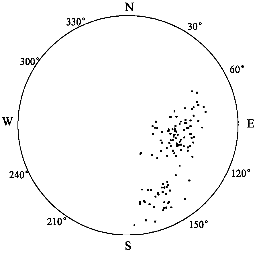
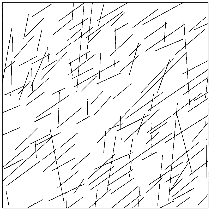
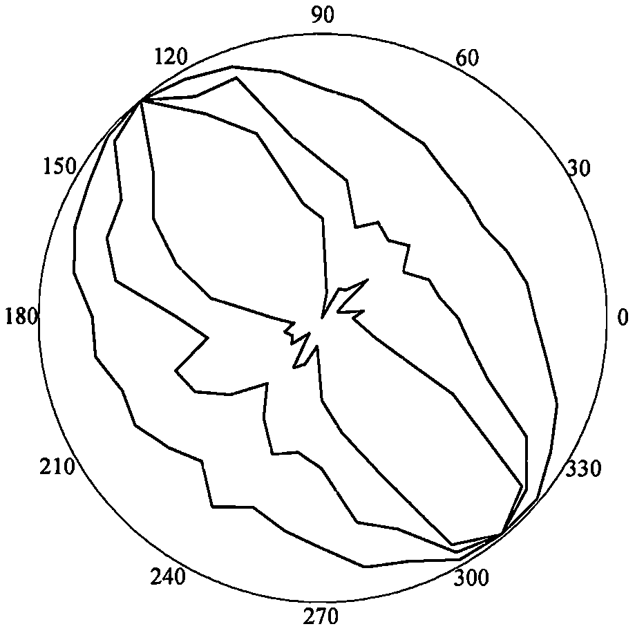
[0208] refer to Figure 1 to Figure 5 , a laser-scanning, BQ, RQD-based t Anisotropic Q anisotropy solution method, including the following steps:

[0209] 1) Rapid acquisition of structural plane 3D laser scanning, the process is as follows:

[0210] 1.1: According to the scanning target and site conditions, select the location of the scanning machine and set up a tripod. During the erection, it is necessary to ensure that the instrument can completely obtain the three-dimensional point cloud information of the slope rock mass according to a certain scanning route, and at the same time, the tripod table should be ensured as much as possible. level, and place control targets;

[0211] 1.2: Place the scanner host on the tripod table, fix the knob, center the bubble of the host by coarsely adjusting the tripod and fine-tuning the scanner base, and set the scanner port p...


PUM


Abstract

A Q anisotropy solving method based on laser scanning, BQ and RQDt anisotropy belongs to the field of Q anisotropy solving, and comprises the following steps: (1) quickly obtaining structural plane three-dimensional laser scanning; (2) drawing a structural surface pole diagram and an inclined rose diagram; (3) performing rock mass quality calculation based on a BQ index; (4) generating and sectioning a rock mass three-dimensional fracture network model; (5) drawing an RQDt anisotropy diagram; (6) performing an optimal threshold t solving method based on BQ inversion; (7) performing an RQDt anisotropy solving method; and (8) performing a Q anisotropy solving method. According to the invention, three-dimensional laser scanning, an affinity propagation algorithm, a BQ theory, a fracture network model, a generalized RQD theory and inversion calculation are combined, the optimal threshold t and anisotropy of RQDt are solved, Q anisotropy is solved, and the Q anisotropy solving method basedon laser scanning, BQ and RQDt anisotropy is provided. The method is clear, and is suitable for anisotropy solution of the rock mass Q.

Description

technical field [0001] The invention relates to a method based on laser scanning, BQ, RQD t Anisotropic Q anisotropy solution method, especially the present invention is based on three-dimensional laser scanning, nearest neighbor propagation algorithm, BQ index, crack network model and generalized RQD theory, inversion calculates RQD t The range of optimal threshold t and the optimal threshold t value, gives the RQD t Anisotropic solution method, and based on RQD t Anisotropy, the solution method of Q anisotropy is given, and a method based on laser scanning, BQ, RQD is provided t The method for solving anisotropic Q anisotropy belongs to the field of solving Q anisotropy. Background technique [0002] The appearance and quality of the rock mass strongly depend on the degree of anisotropy of the rock mass, and the stability of the rock mass is determined by the quality of the rock mass. Some geological phenomena have also proved this point. For example, during the excav...

Claims


Application Information

Patent Timeline
IPC IPC(8): G06Q10/06G06F30/20G06F30/13G06F7/58G01B11/24G06T11/20G06T17/00G06K9/62
CPCG06Q10/06393G06Q10/06395G06F30/20G06T17/00G06F7/588G06T11/203G06T11/206G06F30/13G01B11/24G06F18/23213
Inventor 胡高建刘杰张贺
Owner SHAOXING UNIVERSITY
Learn More