Photovoltaic module

A photovoltaic module and reflective technology, which is applied in photovoltaic power generation, electrical components, semiconductor devices, etc., can solve problems such as battery splits, achieve reliable connections, improve long-term reliability, and reduce the risk of splits

Pending Publication Date: 2020-12-25
CSI CELLS CO LTD +1
View PDF0 Cites 1 Cited by
  • Summary
  • Abstract
  • Description
  • Claims
  • Application Information

AI Technical Summary

Problems solved by technology

However, during the processing of photovoltaic modules, when the length of the ribbon is long or offset, part of the reflective segment may be located on the back of the adjacent cell, resulting in the risk of cracks in the cell

Method used


Image

  • Photovoltaic module
  • Photovoltaic module
  • Photovoltaic module

Examples


Embodiment 1

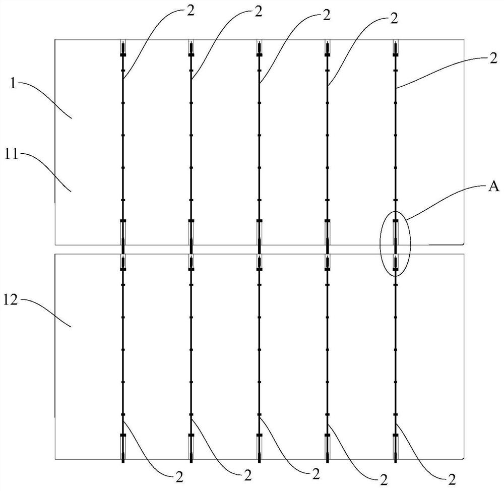
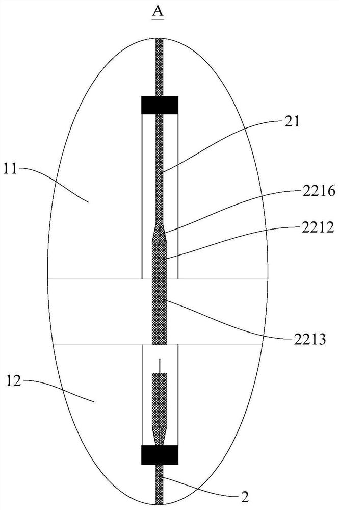
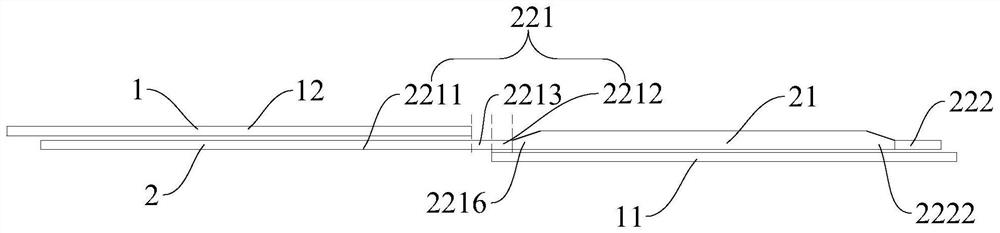
[0062] In this example, if Figure 1a-Figure 1c and image 3 As shown, the photovoltaic module is a patchwork module, and there is a gap between the first battery piece 11 and the second battery piece 12 . The interconnection structure 2 from right to left is the second connection section 222, the second transition section 2222, the reflective section 21, the first transition section 2216, the second sub-connection section 2212, the third sub-connection section 2213 and the first sub-section. Connection section 2211. The entire interconnection structure 2 can be an integral molding, that is, the second connecting section 222, the second transition part 2222, the reflective section 21, the first transition part 2216, the second sub-connecting section 2212, the third sub-connecting section 2213 and The first sub-connection section 2211 is integrally formed during processing, and their materials can be the same without obvious dividing lines. The widths of the second connectio...

Embodiment 2

[0066] In this example, if Figure 2a-Figure 2c and image 3 As shown, the photovoltaic module is a shingled module, and the ends of the first cell 11 and the second cell 12 are overlapped. The interconnection structure 2 from right to left is the second connecting section 222, the second transition section 2222, the reflective section 21, the first transition section 2216, the second sub-connecting section 2212, the fourth sub-connecting section 2214 and the first sub-section. Connection section 2211. The entire interconnection structure 2 can also be an integral molding, that is, the second connecting section 222, the second transition part 2222, the reflective section 21, the first transition part 2216, the second sub-connecting section 2212, and the fourth sub-connecting section 2214 It is integrally formed with the first sub-connection section 2211 during the process, and their materials can be the same, and there is no obvious dividing line. The widths of the second c...


PUM


Abstract

The invention discloses a photovoltaic module, and the photovoltaic module comprises a plurality of battery pieces and a plurality of interconnection structural parts. Two adjacent battery pieces in the plurality of battery pieces are respectively a first battery piece and a second battery piece; each interconnection structural part comprises a light reflecting section and connecting sections, theconnecting sections comprise a first connecting section and a second connecting section, the first connecting section and the second connecting section are connected to the two ends of the light reflecting section respectively, at least one part of the first connecting section is in a flat shape, and at least one part of the second connecting section is in a flat shape; the reflecting section isnon-flat, the reflecting section and the second connecting section are both connected to the front surface of the first battery piece, and at least one part of the first connecting section is connected to the back surface of the second battery piece. According to the photovoltaic module provided by the invention, the reflecting sections can be prevented from being positioned on the back surface ofthe battery piece, so that the risk of battery piece cracking can be effectively reduced, firm connection with the front surface of the battery piece can be realized, and the reliability of the photovoltaic module is improved.

Description

technical field [0001] The invention relates to the technical field of photovoltaic power generation, in particular to a photovoltaic module. Background technique [0002] In the related art, the reflective section of the solder ribbon is usually connected to the front of the battery sheet to improve the output power of the photovoltaic module. However, during the processing of photovoltaic modules, when the length of the solder ribbon is long or offset, part of the reflective segment may be located on the back of the adjacent cell, resulting in the risk of cracks in the cell. Contents of the invention [0003] The present invention aims to solve at least one of the technical problems existing in the prior art. Therefore, an object of the present invention is to provide a photovoltaic module, which can prevent the reflective segment from falling into the back of the battery sheet, thereby effectively reducing the risk of cracking. [0004] The photovoltaic module accordi...

Claims


Application Information

Patent Timeline
IPC IPC(8): H01L31/05H01L31/054
CPCH01L31/0508H01L31/0547Y02E10/52
Inventor 吴艳芬贾行董经兵
Owner CSI CELLS CO LTD
Why Eureka
Try Eureka