
Dynamic hydraulic deflection real-time tracking compensation mechanism of numerical control bending machine

A real-time tracking and compensating mechanism technology, applied in metal processing, metal processing equipment, safety equipment, etc., can solve the problems of unfavorable CNC bending machine real-time inspection, large deviation angle, damaged parts, etc., to achieve real-time inspection and convenience Adjustment effect

Pending Publication Date: 2020-12-29
江苏麦斯铁机械有限公司
View PDF0 Cites 0 Cited by
  • Summary
  • Abstract
  • Description
  • Claims
  • Application Information

AI Technical Summary

Problems solved by technology

[0004] The purpose of the present invention is to provide a dynamic hydraulic deflection real-time tracking compensation mechanism of a numerical control bending machine to solve the problem that the numerical control bending machine on the market proposed in the background technology is difficult to disassemble the shell of the numerical control bending machine, which is not conducive to numerical control Real-time inspection of bending machine, dynamic hydraulic deflection adjustment parts, inconvenient daily replacement, damaged parts, disassembled parts, difficult installation of spare dynamic hydraulic deflection parts, and excessive deviation angle

Method used


Image

  • Dynamic hydraulic deflection real-time tracking compensation mechanism of numerical control bending machine
  • Dynamic hydraulic deflection real-time tracking compensation mechanism of numerical control bending machine
  • Dynamic hydraulic deflection real-time tracking compensation mechanism of numerical control bending machine

Examples


Embodiment Construction

[0026] The following will clearly and completely describe the technical solutions in the embodiments of the present invention with reference to the accompanying drawings in the embodiments of the present invention. Obviously, the described embodiments are only some, not all, embodiments of the present invention. Based on the embodiments of the present invention, all other embodiments obtained by persons of ordinary skill in the art without making creative efforts belong to the protection scope of the present invention.

[0027] In the description of the present invention, unless otherwise stated, the meaning of "plurality" is two or more; the terms "upper", "lower", "left", "right", "inner", "outer" , "front end", "rear end", "head", "tail", etc. indicate the orientation or positional relationship based on the orientation or positional relationship shown in the drawings, and are only for the convenience of describing the present invention and simplifying the description, rather...


PUM


Abstract

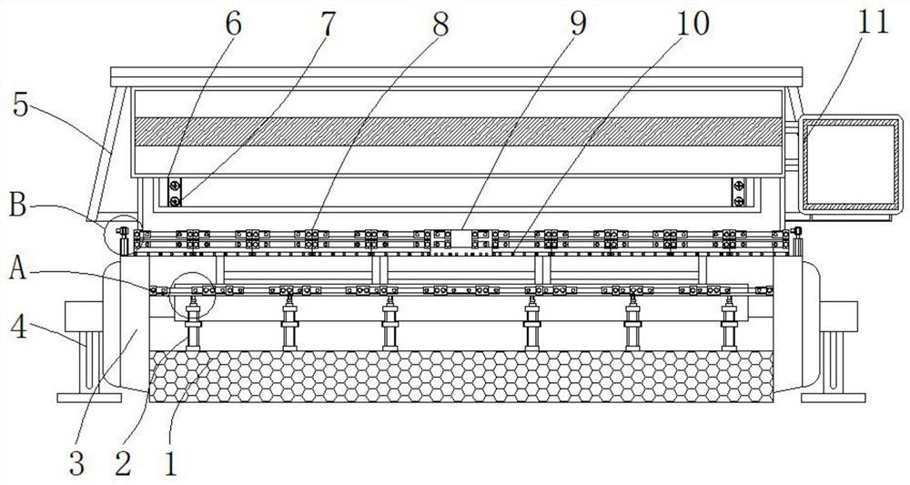
The invention relates to a dynamic hydraulic deflection real-time tracking compensation mechanism of a numerical control bending machine. The dynamic hydraulic deflection real-time tracking compensation mechanism of the numerical control bending machine comprises a base frame, a lifting rod and infrared emitters, wherein a hydraulic cylinder is arranged in the base frame; sliding plate frames arearranged on two sides of the interior of the base frame; supporting columns are arranged on two sides of the exterior of the sliding plate frames; a bolt column frame is arranged at the top end of theouter part of the base frame; bending grooves are formed in the top end of the bolt column frame; a model set frame is arranged at the rear ends of the bending grooves; a protective cover is arrangedat the top end of the model set frame; and a combined cover is arranged in the protective cover. The dynamic hydraulic deflection real-time tracking compensation mechanism of the numerical control bending machine provided by the invention has the beneficial effects that the infrared emitters on rotating columns can rotate along two sides of the bending grooves, after parts between the bending grooves are installed, the infrared emitters are started, infrared rays of the infrared emitters can be corrected along the positions between the bending grooves, and the installation angle deviations ofthe parts in the bending grooves are prevented.

Description

technical field [0001] The invention relates to the technical field of numerical control bending machines, in particular to a dynamic hydraulic deflection real-time tracking compensation mechanism of a numerical control bending machine. Background technique [0002] Under the same load, the deflection of the table and slider of the 10-foot machine is four times that of the 5-foot machine. This means that shorter machines require less shim adjustments to produce acceptable parts. Reducing gasket adjustments shortens preparation time. Material grade is also a key factor. Compared with mild steel, stainless steel usually requires about 50% more load, while most grades of soft aluminum reduce about 50%. CNC bending machine Using hydraulic transmission, the slider part is composed of slider, oil cylinder and mechanical stop fine-tuning structure. The left and right oil cylinders are fixed on the frame, and the piston (rod) drives the slider to move up and down through hydraulic ...

Claims


Application Information

Patent Timeline
IPC IPC(8): B21D11/00B21D11/22B21D55/00B21C51/00
CPCB21C51/00B21D11/00B21D11/22B21D55/00
Inventor 何丽娜
Owner 江苏麦斯铁机械有限公司
Learn More