Automobile part stamping die

A technology for stamping dies and auto parts, which is applied in the field of stamping equipment for auto parts, and can solve the problems of heavy mold weight, complexity, and inconvenient replacement and transportation of parts

Pending Publication Date: 2020-12-29
重庆智者炎麒科技有限公司
View PDF5 Cites 2 Cited by
  • Summary
  • Abstract
  • Description
  • Claims
  • Application Information

AI Technical Summary

Problems solved by technology

It can be seen from this that the stamping device in the prior art needs to replace a large number of molds of different specifications for the same workpiece to achieve stamping at different angles or cu

Method used


Image

  • Automobile part stamping die
  • Automobile part stamping die
  • Automobile part stamping die

Examples


Embodiment 1

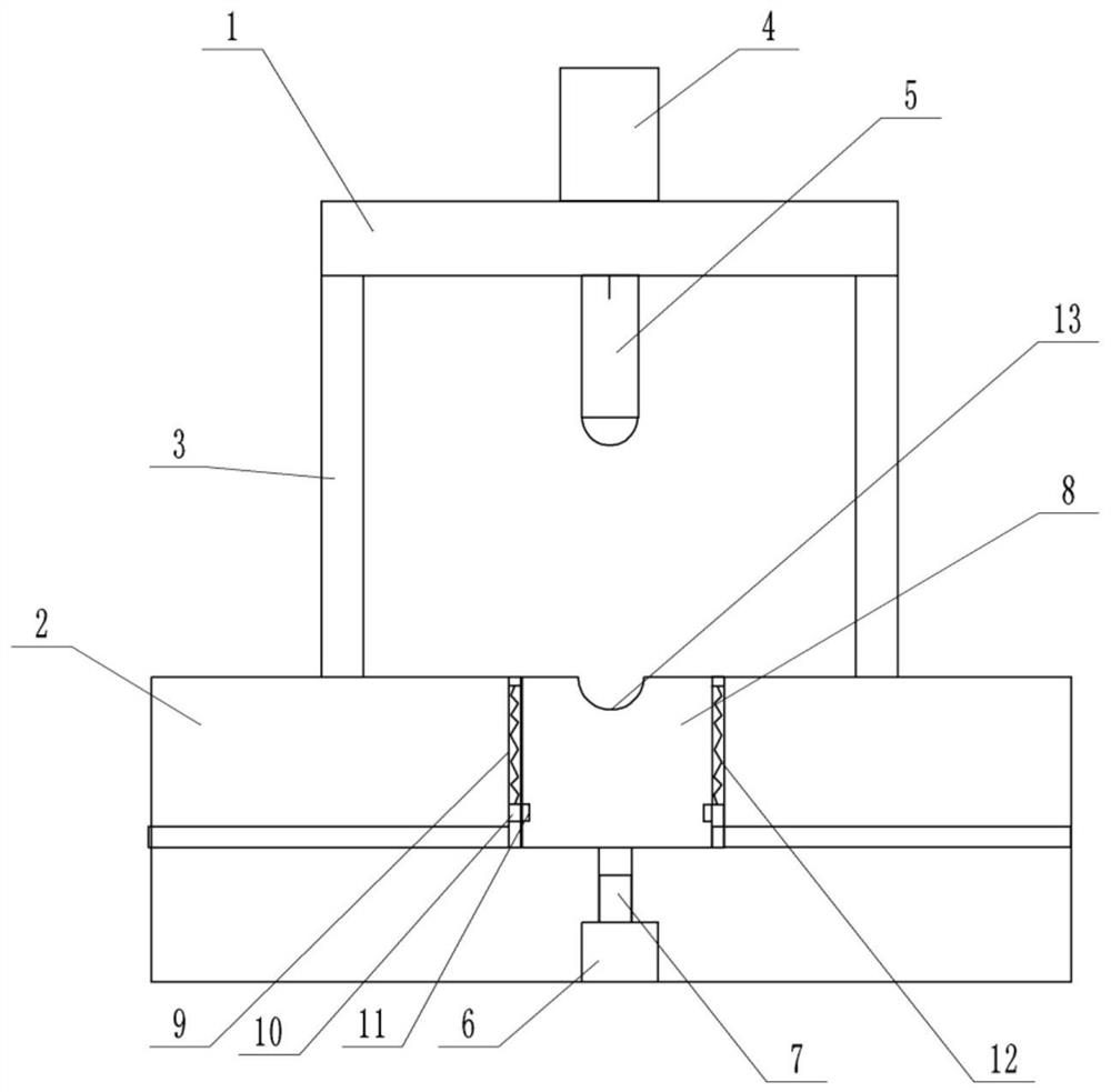
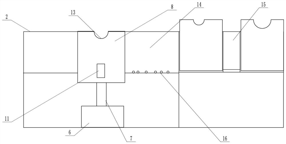
[0025] Such as Figure 1-3 As shown, a stamping die for auto parts includes a base 2, a support frame 3 is provided on both sides of the base 2, a mounting frame 1 is provided on the top of the support frame 3, and a hydraulic pressure for stamping is provided on the mounting frame 1. Cylinder 4, the output end of the hydraulic cylinder 4 is provided with a stamping head 5, the middle part of the base 2 is provided with a stamping groove, the bottom of the stamping groove is provided with a through hole, the area of ​​the through hole is smaller than the area of ​​the stamping groove, and the base 2 is provided with a chute 14, the chute 14 communicates with the side wall of the punching groove, the depth of the chute 14 is smaller than the punching groove; the end of the chute 14 away from the punching groove is provided with a mold switching device.

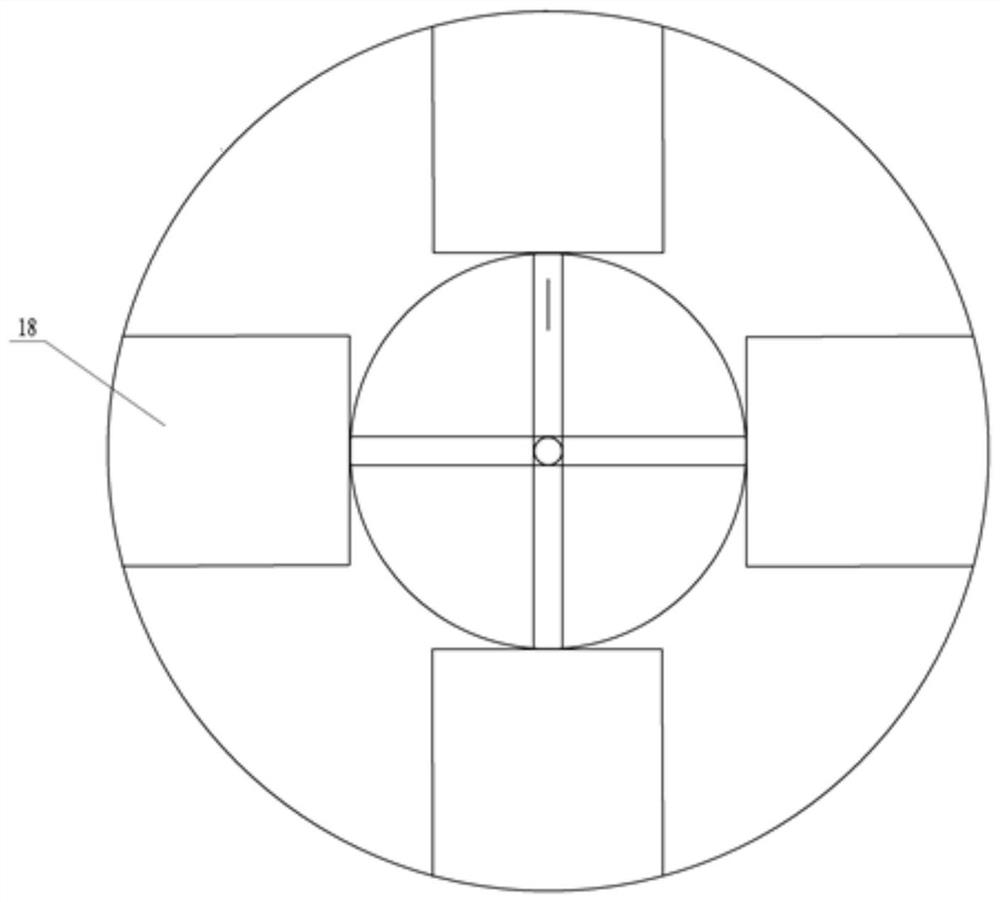
[0026] The mold switching device includes a groove that is rotatably arranged on the base 2, and a turntable 15 is connected ...


PUM


Abstract

The invention provides an automobile part stamping die. The automobile part stamping die comprises a base, supporting frames are arranged on the two sides of the base, a mounting frame is arranged atthe tops of the supporting frames, a hydraulic cylinder for stamping is arranged on the mounting frame, a stamping head is arranged at the output end of the hydraulic cylinder, a stamping groove is formed in the middle of the base, and a through hole is formed in the bottom of the stamping groove. The area of the through hole is smaller than that of the stamping groove, a sliding groove is formedin the base, the sliding groove communicates with the side wall of the stamping groove, and the depth of the sliding groove is smaller than that of the stamping groove. A die switching device is arranged at the end, away from the stamping groove, of the sliding groove. The scheme of the automobile part stamping die is convenient for module replacement, simple to operate and high in efficiency.

Description

technical field [0001] The invention belongs to the technical field of stamping equipment for auto parts, and in particular relates to a stamping die for auto parts. Background technique [0002] Auto parts contain a large number of plates, the pre-bending die set for pre-bending the side ends of the plates, the initial bending die set for processing the pre-bent plates at the position to be rolled, and the initial bending die set for the pre-bending die set The re-bending die set processed at the position of the processed plate to be rolled will rewind the plate after the re-bending die set to form the re-bending die set of the product. It can be seen from this that the stamping device in the prior art needs to replace a large number of molds of different specifications for the same workpiece to achieve stamping at different angles or curvatures. The operation process is slow and complicated, and the molds of different types are often very heavy. It is extremely inconvenie...

Claims


Application Information

Patent Timeline
IPC IPC(8): B21D37/10B21D22/08
CPCB21D37/10B21D22/08
Inventor 马金凤
Owner 重庆智者炎麒科技有限公司
Why Eureka
Try Eureka