Suspension transfer device

A technology of transfer device and traction device, which is applied in welding equipment, laser welding equipment, metal processing equipment, etc., can solve the problems of low hanging operation efficiency, and achieve the effect of improving hanging operation efficiency and improving stability.

Pending Publication Date: 2020-12-29
日照兴业汽车配件股份有限公司
View PDF0 Cites 0 Cited by
  • Summary
  • Abstract
  • Description
  • Claims
  • Application Information

AI Technical Summary

Problems solved by technology

[0006] In view of the above defects, the object of the present invention is to provide a suspension transfer device, aiming to solve the technical problem of low suspension operation efficiency in the prior art

Method used


Image

  • Suspension transfer device
  • Suspension transfer device
  • Suspension transfer device

Examples


Embodiment Construction

[0034] Below in conjunction with accompanying drawing, further elaborate the present invention.

[0035] The orientations involved in this specification are based on the normal working orientation of the suspension transfer device of the present invention, and are not limited to the orientations during storage and transportation, and only represent relative positional relationships, not absolute positional relationships.

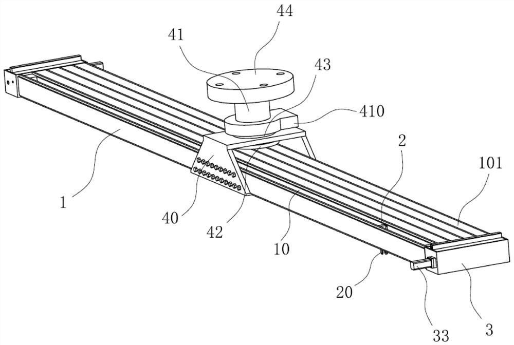
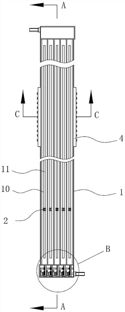
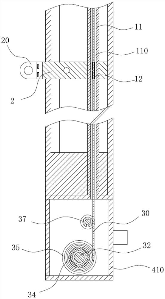
[0036] Such as figure 1 , figure 2 , image 3 , Figure 4 , Figure 5 as well as Figure 6 Commonly shown, the suspension transfer device includes a first mounting frame 1, the middle part of the first mounting frame 1 is equipped with a mounting seat 4, the mounting seat 4 is located above the first mounting frame 1, and several tracks 10 are arranged in the first mounting frame 1 , in this embodiment, five sets of rails 10 are provided, and the rails 10 communicate with the top and bottom surfaces of the first installation frame 1, so that a top open...


PUM


Abstract

The invention relates to the technical field of suspension devices and discloses a suspension transfer device. The suspension transfer device comprises a first mounting rack, wherein a mounting seat is mounted in the middle of the first mounting rack and is located above the first mounting rack, a plurality of rails are arranged in the first mounting rack, and the rails communicate to the plate surface of the first mounting rack; the length direction of the rails is consistent with the length direction of the first mounting rack, the rails are arranged in the width direction of the first mounting rack in a spaced manner, sliding bodies are mounted in the rails, and the bottom ends of the sliding bodies extend to the position below the first mounting rack and are connected to hanging parts.The suspension transfer device solves the technical problem that in the prior art, the suspension operation efficiency is low. The suspension transfer device has the advantages of high operation efficiency, wide operation coverage area and stable device performance, and can be used for both manual traction and electric control operation.

Description

technical field [0001] The invention relates to the technical field of suspension devices, in particular to a suspension transfer device. Background technique [0002] In the workshop, many tools need to be hung and used for traction. Taking the laser marking machine as an example, the laser marking machine is used to mark on the longitudinal beam. In order to improve the convenience of use, the laser marking machine is connected to the rail frame through a balancer. On the sliding body, the guide rail frame is used to fix the high position in the workshop. The transfer of the laser marking machine is realized by sliding the sliding body in the guide rail to meet the needs of marking at various positions. This method has the following problems: [0003] 1. One guide rail can only be used by one laser marking machine, and other tools that need to be suspended are connected to the guide rail in a criss-cross arrangement at high places in the workshop, resulting in frequent int...

Claims


Application Information

Patent Timeline
Patent Type & Authority Applications(China)
IPC IPC(8): B23K26/362B23K26/70
CPCB23K26/362B23K26/702
Inventor 孙鲁生
Owner 日照兴业汽车配件股份有限公司
Why Eureka
Try Eureka