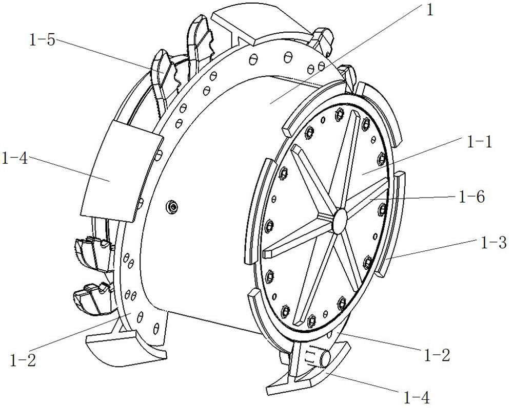
Sludge in-situ stirrer

A mixer, in-situ technology, applied in the direction of cement mixing equipment, clay preparation equipment, soil protection, etc., can solve hydraulic motor stuck, stuck, containing some hard gravel, stone chips, sand, etc. problems, to achieve the effect of preventing power tilt

Pending Publication Date: 2020-12-29
宁波恩特重工科技有限公司
View PDF0 Cites 1 Cited by
  • Summary
  • Abstract
  • Description
  • Claims
  • Application Information

AI Technical Summary

Problems solved by technology

Most of the components in the silt layer are ultra-soft soils such as underconsolidated soil, expansive soil, collapsible loess, and liquefiable soil, and may also contain some hard gravel, stone chips, sand, etc., the mixing drum In order to mix the sludge and cement slurry evenly, the hard gravel, stone chips, sand, etc. must also be broken, otherwise once the mixing drum is blocked, it will cause jamming, resulting in the corresponding hydraulic motor jamming or failure

Method used


Image

  • Sludge in-situ stirrer
  • Sludge in-situ stirrer
  • Sludge in-situ stirrer

Examples


Embodiment Construction

[0023] For a better understanding of the application, various aspects of the application will be described in more detail with reference to the accompanying drawings. It should be understood that these detailed descriptions are descriptions of exemplary embodiments of the application only, and are not intended to limit the scope of the application in any way. Throughout the specification, the same reference numerals refer to the same elements.

[0024] In the drawings, the thickness, size and shape of objects have been slightly exaggerated for convenience of illustration. The drawings are merely examples and are not strictly drawn to scale.

[0025] It should also be understood that the terms "comprising", "having", "comprising" and "comprising", when used in this specification, mean that the features, integers, steps, operations, elements and / or components exist, But it does not exclude the presence or addition of one or more other features, entities, steps, operations, ele...


PUM


Abstract

The invention provides a sludge in-situ stirrer. The sludge in-situ stirrer comprises an extension arm, wherein two stirring drums and a double-stirring-drum hydraulic driving oil way system for driving the stirring drums to rotate are arranged on the extension arm, the double-stirring-drum hydraulic drive oil way system involves a system oil inlet pipe, a system oil return pipe, an oil inlet valve block, an oil return valve block, two motor oil inlet pipes, two motor oil return pipes and two hydraulic motors installed inside the two stirring drums, the system oil inlet pipe is connected withthe two motor oil inlet pipes through the oil inlet valve block, the two motor oil return pipes are connected to the system oil return pipe through the oil return valve block, oil inlets and oil return ports of the two hydraulic motors are connected with the two motor oil inlet pipes and the two motor oil return pipes respectively, the two hydraulic motors are connected in parallel, and a flow balance valve is installed inside the oil inlet valve block or the oil return valve block. The sludge in-situ stirrer can automatically increase the working capacity of the hindered hydraulic motors, sothat the stirring drums break through resistance to continue to normally work, and the stirring drums are prevented from being hindered and stuck.

Description

technical field [0001] The invention relates to the technical field of sludge treatment equipment, and more specifically relates to a sludge in-situ mixer. Background technique [0002] With the rapid development of coastal cities in the southeast, engineering construction has increased sharply, and most of the engineering construction in the coastal cities in the southeast has encountered serious problems such as soft soil, deep silt layer, and scarcity of backfill. Due to the limitations of environmental protection and traditional mountain backfilling methods and the increase in cost, it is increasingly difficult to obtain high-quality filler resources. Therefore, land reclamation projects, marine beach reclamation, and artificial island projects mainly use ultra-soft soil such as backfill and dredged silt. , waste sludge, etc. However, these newly filled soils or the original beach soils are generally dominated by silt or ultra-soft soils, with extremely low strength, an...

Claims


Application Information

Patent Timeline
Patent Type & Authority Applications(China)
IPC IPC(8): E02D3/12B28C5/08
CPCB28C5/08B28C5/0806B28C5/085E02D3/126
Inventor 雷刚
Owner 宁波恩特重工科技有限公司
Why Eureka
Try Eureka