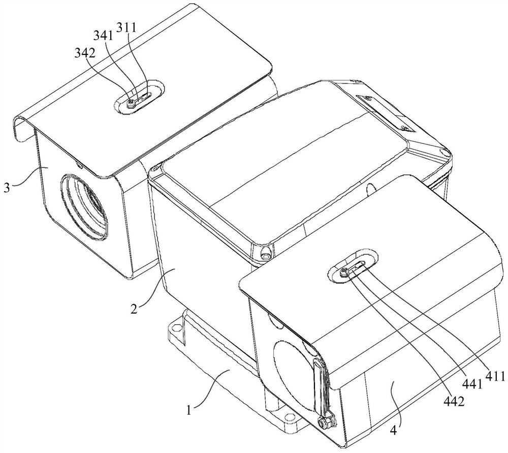
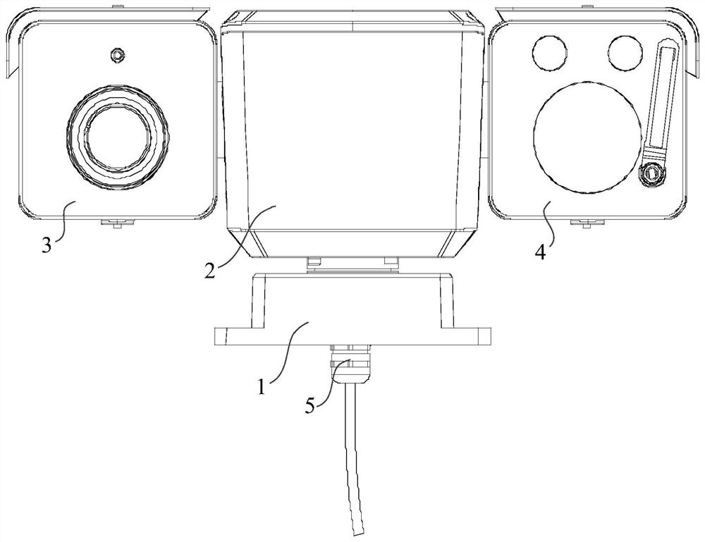
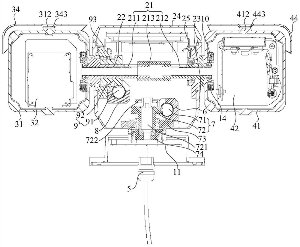
Cloud platform camera

A pan-tilt camera and pan-tilt technology, applied in the field of photography, can solve the problems of the pan-tilt with large volume and large space occupation, and achieve the effect of small volume, compact structure, and few transmission stages

Active Publication Date: 2020-12-29
HANGZHOU HIKMICRO SENSING TECH CO LTD
View PDF6 Cites 0 Cited by
  • Summary
  • Abstract
  • Description
  • Claims
  • Application Information

AI Technical Summary

Problems solved by technology

[0003] However, due to the cooperation of various transmission connectors in the pan-tilt of the existing pan-tilt camera, the pan-tilt is bulky and takes up a lot of space.

Method used


Image

  • Cloud platform camera
  • Cloud platform camera
  • Cloud platform camera

Examples


Embodiment Construction

[0074] In order to have a clearer understanding of the technical features, purposes and effects of the invention, the specific implementation manners of the present invention will now be described with reference to the accompanying drawings, in which the same reference numerals represent the same parts.

[0075] In this article, "schematic" means "serving as an example, example or illustration", and any illustration or implementation described as "schematic" should not be interpreted as a more preferred or more advantageous Technical solutions.

[0076] In order to make the drawings concise, the figures in each figure only schematically show the relevant parts of the present invention, and do not represent the actual structure of the product. In addition, to make the drawings concise and easy to understand, in some drawings, only one of the components having the same structure or function is schematically shown, or only one of them is marked.

[0077]In this article, "upper",...


PUM


Abstract

The invention provides a cloud platform camera. According to the cloud platform camera, a worm gear is adopted for being directly connected between a drive device and a driven part, the number of transmission levels between the drive device and the driven part is small, the transmission efficiency is high, other transmission parts are omitted, thus the size of a cloud platform is small, the structure is compact, the size of the overall cloud platform camera is small, and the integration degree is high.

Description

technical field [0001] The invention relates to the technical field of photography, in particular to a pan-tilt camera. Background technique [0002] The pan-tilt camera is used to take pictures of the surrounding environment. In order to achieve a wider shooting range, the pan-tilt generally drives the camera to rotate to achieve full coverage of the circumferential range of the camera. In order to realize that the pan-tilt drives the camera to rotate, a power device and various transmission connectors are arranged inside the pan-tilt, and through the transmission cooperation of each connector, the circumferential full coverage of the shooting range of the camera is realized. [0003] However, due to the cooperation of various transmission connectors in the pan-tilt of the existing pan-tilt camera, the pan-tilt is bulky and occupies a large space. Contents of the invention [0004] In order to solve the above technical problems, the present invention provides a pan-tilt ...

Claims


Application Information

Patent Timeline
Patent Type & Authority Applications(China)
IPC IPC(8): F16M11/12F16M11/18H04N5/225H04N5/232H04N5/247
CPCF16M11/121F16M11/18F16M2200/024H04N23/50H04N23/51H04N23/695H04N23/90
Inventor 何健陈新友张松松
Owner HANGZHOU HIKMICRO SENSING TECH CO LTD
Why Eureka
Try Eureka