Height-adjustable rack and refrigerator

An adjustable shelf technology, which is applied to household refrigeration devices, lighting and heating equipment, household appliances, etc., can solve the problems of complex structure of electric devices, high manufacturing cost, failure of lifting mechanism, etc., and achieve simple structure, easy installation and Low maintenance cost and low manufacturing cost

Active Publication Date: 2020-12-29
QINGDAO HAIER MOLDS
View PDF8 Cites 0 Cited by
  • Summary
  • Abstract
  • Description
  • Claims
  • Application Information

AI Technical Summary

Problems solved by technology

Although this patent solves the problem that the height of the shelf cannot be adjusted, the structure of the electric device is complicated, and because the inside of the refrigerator is prone to frost, it is easy to cause the failure of the lifting mechanism, the reliability of use is relatively low, and the manufacturing cost is high. trouble

Method used


Image

  • Height-adjustable rack and refrigerator
  • Height-adjustable rack and refrigerator
  • Height-adjustable rack and refrigerator

Examples


Embodiment 1

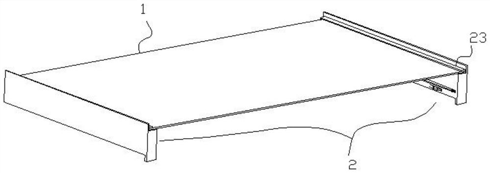
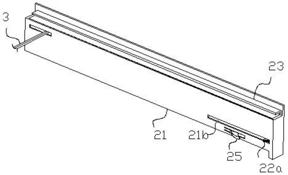
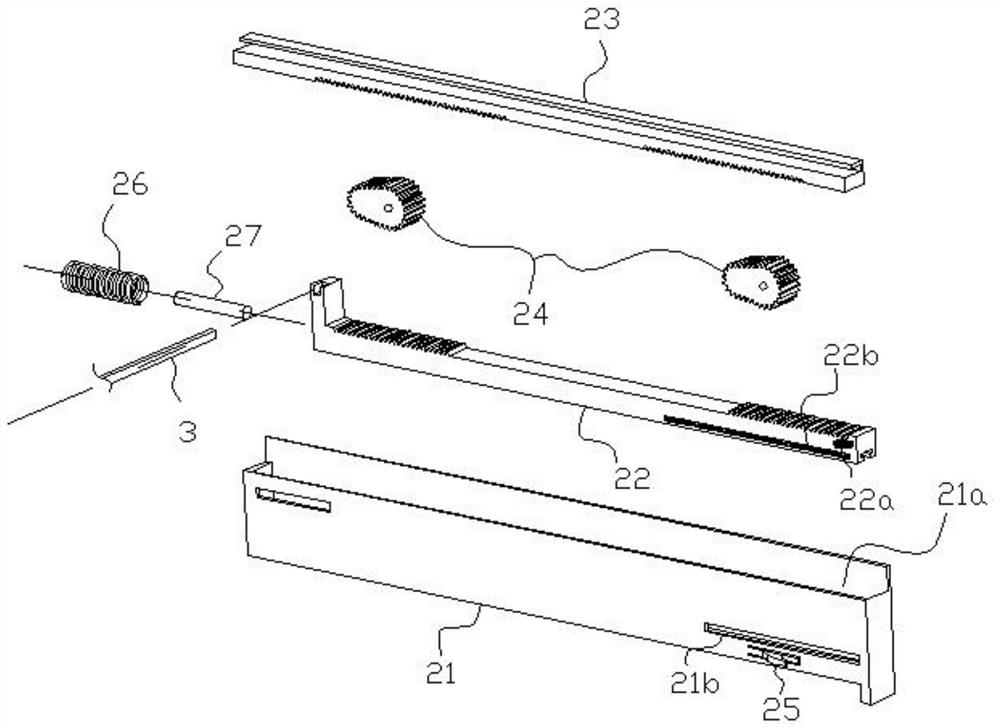
[0040] Such as Figure 1 to Figure 3 As shown, a height-adjustable shelf includes a pair of lifting devices 2 and a shelf 1, and the two lifting devices 2 are symmetrically installed on both sides of the shelf 1, and drive the shelf 1 up and down. The storage board 1 is a square plate, and the lifting device 2 includes a rectangular housing 21 , a lower guide rail 22 , a cam 24 , an upper guide rail 23 and a return spring 26 .

[0041] A strip-shaped sliding cavity 21a is formed inside the housing 21, and at least the upper end of the sliding cavity 21a is an open opening. The lower guide rail 22 is installed on the bottom of the slide chamber 21a, and can slide horizontally in the slide chamber 21a. The width of the lower guide rail 22 is the same as that of the slide chamber 21a, so that the lower guide rail 22 can only slide forward and backward in the slide chamber 21a, that is, along the Sliding along the length direction of the sliding cavity 21a. Preferably, the botto...

Embodiment 2

[0054] combine Figure 8 to Figure 10 As shown, the position-limiting cooperation between the upper guide rail 23 and the sliding chamber 21a in this embodiment is different from that in Embodiment 1. A vertical groove 23a is provided on one side of the upper guide rail 23, and a vertical groove 23a is provided on the inner wall of the sliding chamber 21a. There is a vertical rib 21c with the same width as the vertical groove 23a, and the vertical groove 23a and the vertical rib 21c are slidingly matched up and down to limit the upper guide rail 23 to slide up and down relative to the sliding cavity 21a.

[0055] Such as Figure 11 As shown, the present invention also relates to a refrigerator, which is configured with the height-adjustable shelf described in any of the above-mentioned embodiments, and the refrigerator also includes an inner container 4, the inner container 4 A support structure 41 is provided on the side wall, and the housing 21 is fixedly clamped on the sup...


PUM


Abstract

The invention relates to a height-adjustable rack. The height-adjustable rack comprises a pair of lifting devices and a rack plate, wherein the two lifting devices are symmetrically installed at the two sides of the rack plate, and each lifting device comprises a shell body internally provided with a long-strip-shaped sliding cavity, a lower guide rail installed in the sliding cavity, an upper guide rail located above the lower guide rail, in limiting fit with the sliding cavity and capable of sliding up and down relative to the sliding cavity, and a cam arranged between the upper guide rail and the lower guide rail and in rolling fit with the upper guide rail and the lower guide rail; a pushing structure is arranged on the lower guide rail and capable of pushing the lower guide rail to slide; when the lower guide rail slides, the cam rotates and enables the upper guide rail to move in the vertical direction, and the shelf is connected with the upper guide rail and keeps synchronous movement with the upper guide rail. The invention further relates to a refrigerator provided with the rack. The rack is height-adjustable, simple in structure, good in bearing effect and low in manufacturing cost.

Description

technical field [0001] The invention relates to household appliances, in particular to a height-adjustable shelf and a refrigerator. Background technique [0002] In order to improve the utilization rate of the internal space of the existing household refrigerators, special shelves are generally arranged inside the refrigerators. The shelves of ordinary refrigerators are generally inserted into the refrigerator liner in a pluggable way, and the height is determined by The position of the card slot is determined and cannot be adjusted. This results in that in some cases, due to the insufficient height reserved for the shelf, the items cannot be placed on the shelf smoothly. If the shelf is removed, space will be wasted . At present, some high-end refrigerators are equipped with electric shelves that can be lifted and lowered in the inner tank. For example, the Chinese invention patent application number: 201611037914.0 discloses a synchronization system for lifting and lower...

Claims


Application Information

Patent Timeline
Patent Type & Authority Applications(China)
IPC IPC(8): F25D25/02
CPCF25D25/02
Inventor 毕云龙王淼王金海丁春磊李晓宾付丽英
Owner QINGDAO HAIER MOLDS
Why Eureka
Try Eureka