Supercharge Your Innovation With Domain-Expert AI Agents!

A permanent magnet double rotor vernier motor

A rotor vernier and permanent magnet technology, which is applied in the direction of magnetic circuit rotating parts, electromechanical devices, electrical components, etc., can solve problems such as limited engineering applications, difficulties in processing and manufacturing composite motors, etc., to increase utilization, improve performance, and improve rotation speed effect

Active Publication Date: 2021-07-20
HEFEI UNIV OF TECH
View PDF10 Cites 0 Cited by
  • Summary
  • Abstract
  • Description
  • Claims
  • Application Information

AI Technical Summary

Problems solved by technology

However, the three-layer air gap structure of this composite motor brings great difficulties to the processing and manufacturing, which limits its practical engineering application

Method used


Image

  • A permanent magnet double rotor vernier motor
  • A permanent magnet double rotor vernier motor
  • A permanent magnet double rotor vernier motor

Examples


Embodiment Construction

[0015] The present invention will be further described below in conjunction with accompanying drawing:

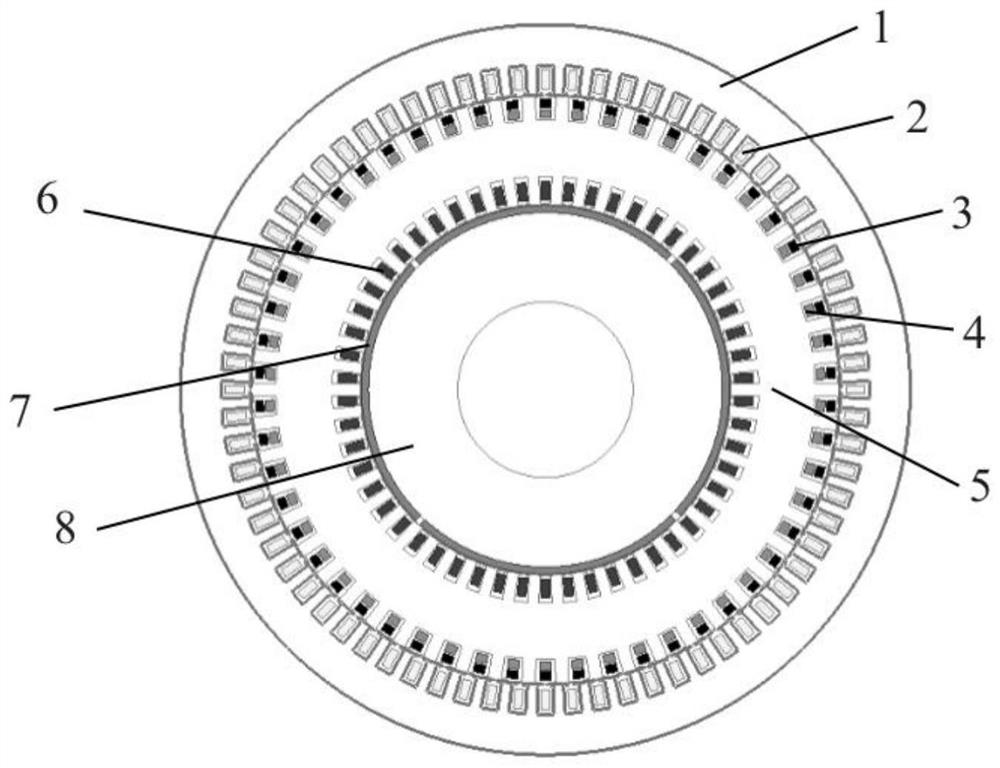
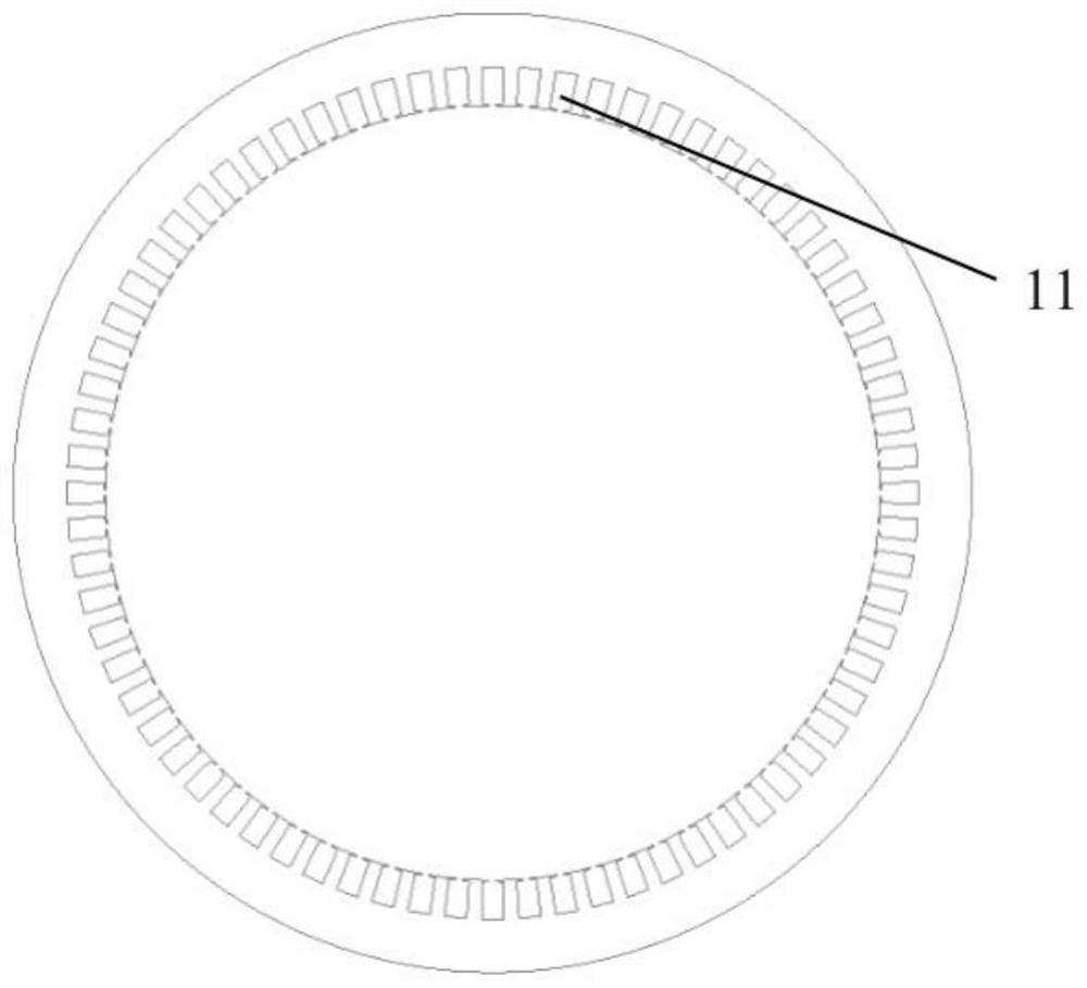
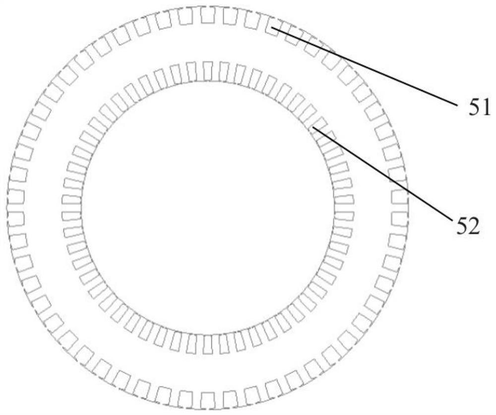
[0016] Such as Figure 1~4 As shown, the permanent magnet dual-rotor vernier motor of this embodiment includes an outer rotor 1, an inner rotor 8 and a stator 5, the stator 5 is located between the outer rotor 1 and the inner rotor 8, and the inner side of the outer rotor 1 is provided with an outer rotor slot 11. The outer rotor slot 11 is embedded with a number of phases (p 2 +p 3 ) of the winding 2, the outside of the stator 5 is provided with an outer stator slot 51, and the outer stator slot 51 is embedded with a number of pole pairs p 2 ,p 3 Two sets of windings 3 and 4, the inner side of the stator 5 is provided with an inner stator slot 52, and the inner stator slot 52 is embedded with a pole pair number p 1 winding 6, the permanent magnet 7 on the inner rotor 8 adopts a surface-mounted installation method, and the number of pole pairs of the permanent magnet 7 ...


PUM


Abstract

The invention relates to a permanent magnet dual-rotor vernier motor, comprising an inner rotor, a stator and an outer rotor, the stator is located between the inner rotor and the outer rotor, an outer rotor groove is arranged on the inner side of the outer rotor, and an outer rotor groove is arranged on the outer side of the stator An outer stator slot is provided, and an inner stator slot is provided on the inner side of the stator. The stator is integrally formed, and the inner rotor is arranged with a pole pair number p 1 permanent magnets, the inner stator slot is provided with a set of pole pairs p 1 For the winding of the magnetic field, two sets are arranged on the outer stator slot to form a pole pair number p 2 ,p 3 The winding of the magnetic field, the number of phases is arranged on the outer rotor slot (p 2 +p 3 ) winding. The invention increases the utilization rate of the motor, improves the rotation speed of the air gap magnetic field, increases the power density of the motor, and improves the performance of the motor.

Description

technical field [0001] The invention relates to the technical field of parallel connection of power supplies, in particular to a permanent-magnet double-rotor vernier motor. Background technique [0002] In recent decades, permanent magnet motors have developed rapidly due to many advantages such as compact structure, high power density and high efficiency. In low-speed and high-torque applications, the direct drive of permanent magnet motor can eliminate the gearbox, eliminate the noise and failure caused by gear transmission, and improve the efficiency and reliability of the system. However, if the traditional permanent magnet synchronous motor is used to achieve the purpose of low speed and high torque, the number of slots, windings and permanent magnet poles will be large, resulting in a relatively large motor size and unsatisfactory indicators such as torque density. In order to achieve low speed and high torque, a variety of composite motors based on the combination o...

Claims


Application Information

Patent Timeline
Patent Type & Authority Patents(China)
IPC IPC(8): H02K16/02H02K1/27H02K1/16H02K3/28H02K21/04H02K51/00
CPCH02K16/02
Inventor 任泰安阚超豪李伟
Owner HEFEI UNIV OF TECH
Features
  • R&D
  • Intellectual Property
  • Life Sciences
  • Materials
  • Tech Scout
  • Unparalleled Data Quality
  • Higher Quality Content
  • 60% Fewer Hallucinations
Learn More