Screw mounting equipment convenient for hole alignment and used for electronic part assembling

A technology for electronic components and installation equipment, which is applied in the field of electronic component assembly, can solve problems such as assembly failure, hole slots, and threaded holes that are not easy to align, and achieve the effect of avoiding slipping

Inactive Publication Date: 2021-01-01
深圳市辉迪机电科技有限公司
View PDF0 Cites 2 Cited by
  • Summary
  • Abstract
  • Description
  • Claims
  • Application Information

AI Technical Summary

Problems solved by technology

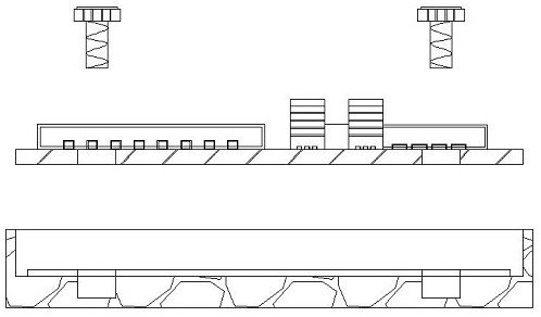
[0004] Aiming at the deficiencies of the prior art, the present invention provides a kind of screw installation equipment for the assembly of electronic parts, which is convenient for hole alignment, which solves the problem of the holes on the surface of the existing circuit board and the protective shell when assembling in the above-mentioned background technology. The slots and threaded holes are not easy to align. Even after the alignment, the screw needs to be aligned twice when the screw penetrates, that is, the screw is aligned with the hole slot and the threaded hole. Multiple alignments will easily lead to assembly failure.

Method used


Image

  • Screw mounting equipment convenient for hole alignment and used for electronic part assembling
  • Screw mounting equipment convenient for hole alignment and used for electronic part assembling
  • Screw mounting equipment convenient for hole alignment and used for electronic part assembling

Examples


Embodiment Construction

[0028] The following will clearly and completely describe the technical solutions in the embodiments of the present invention with reference to the accompanying drawings in the embodiments of the present invention. Obviously, the described embodiments are only some, not all, embodiments of the present invention.

[0029] In the description of the present invention, unless otherwise stated, the meaning of "plurality" is two or more; the terms "upper", "lower", "left", "right", "inner", "outer" , "front end", "rear end", "head", "tail", etc. indicate the orientation or positional relationship based on the orientation or positional relationship shown in the drawings, and are only for the convenience of describing the present invention and simplifying the description, rather than Indicates or implies that the device or element referred to must have a particular orientation, be constructed and operate in a particular orientation, and therefore should not be construed as limiting the...


PUM


Abstract

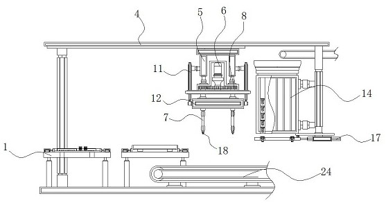
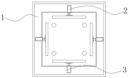
The invention discloses screw mounting equipment convenient for hole alignment and used for electronic part assembling, and relates to the technical field of electronic part assembling. Specifically,the screw mounting equipment convenient for hole alignment and used for electronic part assembling comprises a placement support plate, an assembling rod and a screwdriver blade component; micro pushrods are arranged around the top surface of the placement support plate; the assembling rod penetrates through the interior of a motor box; buffering spring pressure columns are arranged around the top of the inner wall of an assembling box; and the screwdriver blade component is arranged at the bottom of the inner wall of the assembling rod. According to the screw mounting equipment convenient for hole alignment and used for electronic part assembling, the assembling rod, the assembling box and a material receiving plate are matched with one another, so that a circuit board and a protective shell can be positioned, clamped and assembled to guarantee alignment between hole positions and threaded grooves; the material receiving plate receives screws and transfers the screws to the positionunder the assembling rod through an electric push rod; due to the fact that the extending distance of the electric push rod is fixed, secondary positioning is not needed; it is guaranteed that the screws can accurately penetrate through the hole positions to be in threaded connection with the threaded grooves; and therefore, the assembling success rate is increased.

Description

technical field [0001] The invention relates to the technical field of electronic component assembly, in particular to a screw installation device for facilitating hole alignment for electronic component assembly. Background technique [0002] There are several electronic components arranged on the surface of the circuit board. In order to ensure the normal use of the electronic components and the circuit board, the circuit board with the electronic components is often assembled into the protective shell, and the protective shell protects the circuit board, which has the function of improving waterproof, waterproof Dust, anti-collision and other advantages, when assembling, the hole on the surface of the circuit board is usually aligned with the threaded hole on the bottom of the inner wall of the protective shell, and then the screw is screwed to pass through the hole on the surface of the circuit board and the threaded hole inside the protective shell Threaded connection t...

Claims


Application Information

Patent Timeline
Patent Type & Authority Applications(China)
IPC IPC(8): B23P19/00B23P19/06B25B11/02
CPCB23P19/001B23P19/069B25B11/02
Inventor 陈其志潘锐鸿罗琨耀
Owner 深圳市辉迪机电科技有限公司
Why Eureka
Try Eureka