High-bearing bidirectional controllable locking mechanism

A locking mechanism and rod technology, applied in the field of robotics, can solve the problems of poor bearing capacity, complex structure, and single control function, and achieve the effect of simple and reliable control structure, large contact area, and strong bearing capacity

Active Publication Date: 2021-01-01
SHANGHAI UNIV
View PDF5 Cites 0 Cited by
  • Summary
  • Abstract
  • Description
  • Claims
  • Application Information

AI Technical Summary

Problems solved by technology

[0005] The purpose of the present invention is to overcome the deficiencies of the prior art, aiming at the problems of single control function, complex structure, complex control system and poor bearing capacity of the existing locking mechanism, a large load-bearing two-way controllable locking mechanism is proposed

Method used


Image

  • High-bearing bidirectional controllable locking mechanism
  • High-bearing bidirectional controllable locking mechanism
  • High-bearing bidirectional controllable locking mechanism

Examples


Embodiment 1

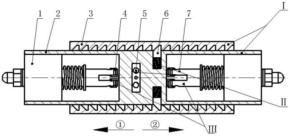
[0033] see figure 1 , a large-load two-way controllable locking mechanism, including an inner / outer rod group I, two pairs of spring slider groups II and two sets of actuators III; the inner / outer rod group I consists of two open ends The outer rod 3 is composed of a sliding sleeve and the inner rod 2, the two groups of actuators III are installed in the inner cavities at both ends of the inner rod 2, and the spring slider group II is installed in the middle of the inner rod 2 in the inner cavity. In the chute of the rod 2, it is connected with the actuator III through the wire rope 4; the actuator III drives the spring slider group II to reciprocate in the chute of the inner rod 2 under the working conditions of the specified combination. movement, to realize the engagement and release of the spring slider group II and the outer rod 3, and then to realize two-way sliding and locking. The locking mechanism of the present invention is applied in the deformable truss system, wh...

Embodiment 2

[0035] This embodiment is basically the same as Embodiment 1, and the special features are as follows:

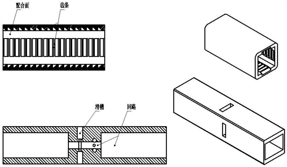
[0036] The inner wall of the outer rod 3 in the inner / outer rod group I is arranged with four sets of rack structures, and the two sets of rack structures that are parallel to each other have the same direction and the same pitch; the directions of the rack structures that are not parallel to each other Instead, the pitches are equal in size.

[0037] Between the inner wall of the outer rod 3 and the inner rod 2, needle rollers, or balls, or miniature sticks, or miniature pulleys are arranged as structures for anti-friction bearing and guiding.

[0038] The middle part of the inner rod 2 in the inner / outer rod group I is arranged with a guide chute for the slider 5 and the slider 6, and the two sliders 5, 6 are connected with the actuator 1, 7 through the wire rope 4 access.

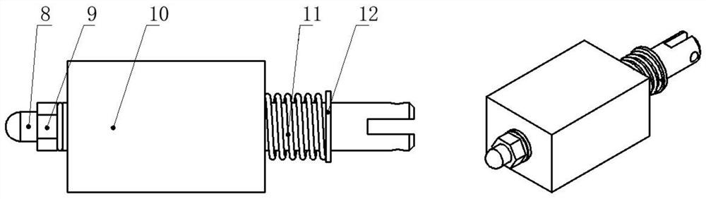
[0039] The spring slider group II is made up of a slider 13 and a spring 14. The front end of th...

Embodiment 3

[0048] Such as figure 2 with image 3 As shown, the inner / outer rod I is composed of an outer rod whose inner wall is a rack structure and an inner rod, and the inner and outer rods are matched by sliding contact.

[0049] Such as figure 2 with Figure 5 As shown, the spring slider group II is arranged in the chute of the inner rod, and the end of the slider is connected to the actuator through a wire rope. In the case of de-energization of the actuator, it locks with the rack structure of the outer rod. By controlling the two actuators, various working states can be controlled to control the sliding and locking of the two rods.

[0050] Such as figure 2 with Figure 4 As shown, the actuator III is composed of an iron core, a nut, an iron ring, a spring and a coil, etc., and is fixed on the inner rod.

[0051] The locking mechanism of this embodiment has four operation methods, including actuators 1 and 7 de-energized, actuators 1 and 7 working, actuator 1 working an...


PUM


Abstract

The invention relates to a high-bearing bidirectional controllable locking mechanism. The locking mechanism comprises brakes, an inner or outer rod group and spring slider groups, wherein the brakes are fixed to an inner rod and connected with sliders through steel wire ropes separately; the spring slider groups are arranged in sliding grooves of the inner rod; when the brakes do not work, the sliders are clamped in an outer rod under the action of springs; when the brakes work, the brakes pull the corresponding sliders, the inner rod and the outer rod are in a free loose state, bidirectionalmovement can be achieved, the working conditions of the brakes can be changed, and the inner rod and the outer rod can achieve four working conditions, such as bidirectional movement, bidirectional locking, one side locking and the other side moving. The spring slider groups are in large-area contact with the outer rod and have high bearing capacity. The locking mechanism is applied to a deformable truss system, and the mechanism stability and the bearing capacity of the system can be significantly improved.

Description

technical field [0001] The invention relates to a large-load bidirectional controllable locking mechanism, which belongs to the field of robots. Background technique [0002] The locking mechanism is an important component of the reconfigurable robot. The reconfigurable robot based on the module can achieve various deformation combinations with the help of the locking mechanism, so that it can adapt to many complex environments and complete various special tasks. At the same time, the locking mechanism can be applied in other related fields, such as realizing the change of the aircraft truss in the aerospace field. [0003] The reconfigurable robot adopts a modular design, and each module is the same for easy installation and maintenance. The locking mechanism is an important component for a reconfigurable robot to achieve various working postures, achieve various working positions and complete various tasks. During the deformation process of the reconfigurable robot, the ...

Claims


Application Information

Patent Timeline
Patent Type & Authority Applications(China)
IPC IPC(8): B25B11/00
CPCB25B11/00
Inventor 田应仲田振宇赵胤君姜汉斌朱义李龙
Owner SHANGHAI UNIV
Why Eureka
Try Eureka