LOGO code printing equipment for information technology chip processor

An information technology and processor technology, applied in the field of information technology chip processor LOGO coding printing equipment, can solve the problems of low production efficiency, error-prone, high labor cost, improve printing standards, realize automatic feeding, Avoid blurry effects

Active Publication Date: 2021-01-01
广州好未来科技研究有限公司
View PDF8 Cites 2 Cited by
  • Summary
  • Abstract
  • Description
  • Claims
  • Application Information

AI Technical Summary

Problems solved by technology

[0004] In order to overcome the disadvantages of high labor cost, low production efficiency and error-prone part of the manual operation of the existing equipment, the purpose of the present invention is to provide an information technology chip processor LOGO code that can realize automatic chip transfer and automatic printing printing equipment

Method used


Image

  • LOGO code printing equipment for information technology chip processor
  • LOGO code printing equipment for information technology chip processor
  • LOGO code printing equipment for information technology chip processor

Examples


Embodiment 1

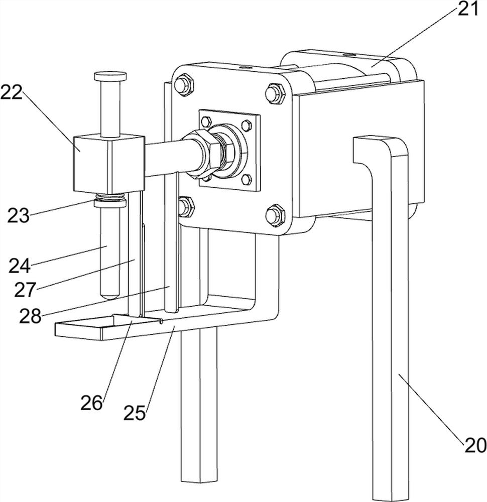
[0083] An information technology chip processor LOGO code printing equipment, such as figure 1 As shown, it includes a base 1, a telescopic mechanism 2 and an up and down mechanism 3, the right side of the top of the base 1 is provided with a telescopic mechanism 2, and the base 1 is provided with an up and down mechanism 3.

[0084] When people need to print the LOGO code on the chip, first pour the paint into the parts of the telescopic mechanism 2, then place the chip under the parts of the upper and lower mechanism 3, and then control the telescopic mechanism 2 so that the parts of the telescopic mechanism 2 will put the paint Continuously smear on the LOGO, and at the same time control the components of the upper and lower mechanism 3 to print the LOGO code on the chip.

Embodiment 2

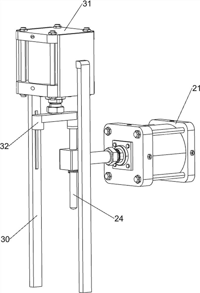
[0086] On the basis of Example 1, such as Figure 2-3 As shown, the telescopic mechanism 2 includes a first pillar 20, a first cylinder 21, a limiter block 22, a first spring 23, a first slider 24, a paint tank 25, a brush plate 26, a first transmission block 27 and a second transmission block. Block 28, the right side of the base 1 is provided with two first pillars 20, the first cylinder 21 is arranged between the first pillars 20, the left side of the first cylinder 21 is provided with a limit block 22, and the limit block 22 is slidingly connected with the first A slide block 24, a first spring 23 is arranged between the top of the first slide block 24 and the limiter block 22, the first spring 23 is set on the outside of the first slide block 24, a paint tank 25 is provided on the left side of the bottom of the first cylinder 21, The paint tank 25 is slidably connected with a brush plate 26, the left side of the first cylinder 21 is provided with a first transmission bloc...

Embodiment 3

[0091] On the basis of Example 2, such as Figure 4-12 As shown, a control mechanism 4 is also included, and the control mechanism 4 includes a first connecting block 40, a second sliding block 41, a second spring 42, a first switch 43, a second connecting block 44, a third sliding block 45, a first Three springs 46 and the second switch 47, the second strut 30 on the front side is provided with the first connecting block 40, the second sliding block 41 is slidably connected on the first connecting block 40, the second sliding block 41 is connected with the first A second spring 42 is arranged between the blocks 40, a first switch 43 is arranged on the right side of the second cylinder 31, and the first switch 43 is in contact with the second slide block 41, and the second support 30 on the rear side is connected with a second connection. block 44, the second connecting block 44 is slidably connected with a third sliding block 45, a third spring 46 is provided between the thir...


PUM


Abstract

The invention relates to printing equipment, in particular to LOGO code printing equipment for an information technology chip processor. The invention aims to provide the LOGO code printing equipmentfor the information technology chip processor, and the LOGO code printing equipment can realize automatic chip transmission and automatic printing. The LOGO code printing equipment for the informationtechnology chip processor comprises a base and a telescopic mechanism, and the telescopic mechanism is arranged at one side of the top of the base; and an up-down mechanism is also included, and thebase is provided with the up-down mechanism. Through cooperation of the telescopic mechanism, the up-down mechanism and a control mechanism, LOGO codes can be automatically printed on chips, manual operation is not needed, and time and labor are saved.

Description

technical field [0001] The invention relates to a printing device, in particular to a LOGO code printing device for an information technology chip processor. Background technique [0002] For rectangular chip surface mount devices, it is necessary to test the specifications and parameters of the finished product after the production is completed. After passing the test, the product is packaged by packaging equipment such as a packaging machine. For chips of different brands, it is necessary to print Make the corresponding LOGO, that is, complete the production of the entire electronic product. [0003] In the process of printing the LOGO corresponding to the chip, it needs to be completed by a separate printing equipment. Now the printing equipment needs to be maintained and used by workers. During the printing process, people need to continuously apply paint and transfer chips. Labor costs are high, production efficiency is low, and manual operations are prone to errors. ...

Claims


Application Information

Patent Timeline
Patent Type & Authority Applications(China)
IPC IPC(8): B65B61/26B41F17/00
CPCB65B61/26B41F17/00
Inventor 曾汝连
Owner 广州好未来科技研究有限公司
Why Eureka
Try Eureka