Linkage door hanging structure and linkage door
A door crane and linkage technology, which is applied in the field of doors and windows, can solve the problems of labor cost, labor and labor, inconvenient installation of wire rope or belt rope, etc., and achieve the effect of simplifying the installation process, reducing the difficulty of installation, and saving labor costs
- Summary
- Abstract
- Description
- Claims
- Application Information
AI Technical Summary
Problems solved by technology
Method used
Image
Examples
Embodiment 1
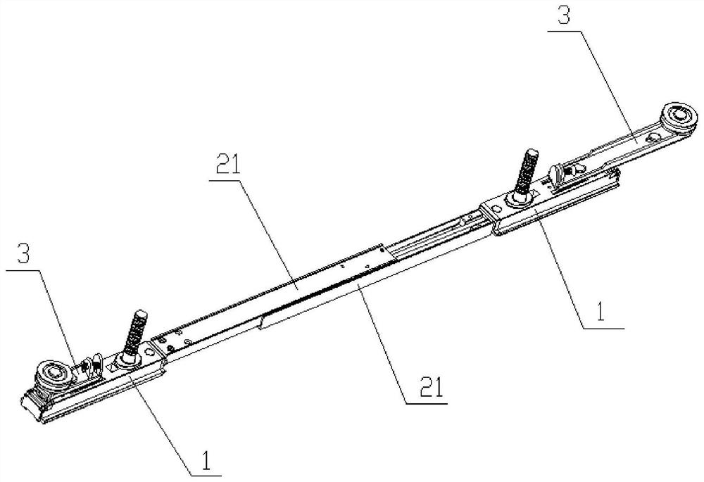
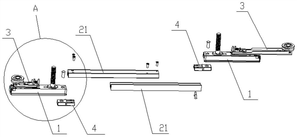
[0047] refer to figure 1 and figure 2 , the invention discloses a linkage door hanging structure, comprising two sets of door frame hanging boxes 1 , a connecting device and two sets of winding wheel devices 3 . Wherein, the two sets of door frame hanging boxes 1 are used to be installed on the top of the door leaf; the door frame hanging boxes 1 are connected to the two door frame hanging boxes 1; the two winding wheel devices 3 are respectively arranged on the two The upper end of door frame hanging box 1. Wherein, the structures and functions of the two sets of winding reel devices 3 are consistent, and the technical effects achieved are the same, and the difference between the two is only the difference in size, and the difference in the number and installation position of the pin 324 and the waist-shaped hole 323 . The invention also discloses a linked door with the hanging structure of the linked door.
[0048] During the installation process of the linked door, the ...
Embodiment 2
[0060] refer to Figure 7 to Figure 9 , The difference between Embodiment 2 and Embodiment 1 is in the technical feature: the difference of the adjustment rod.
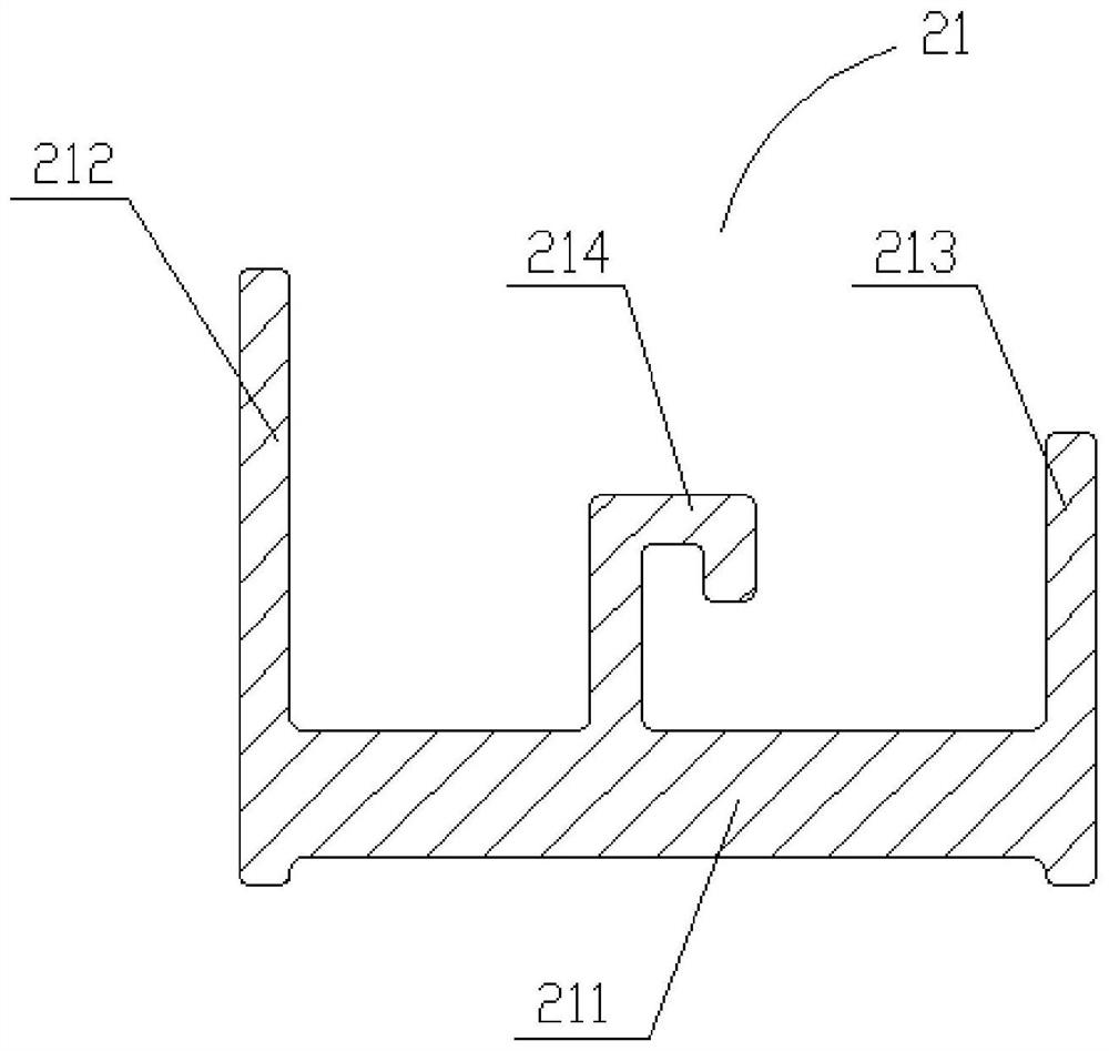
[0061] In this embodiment, the cross section of the adjusting rod 21 is roughly H-shaped, including a bottom edge 211, a first vertical edge 212 and a second vertical edge 213 connected to the two ends of the bottom edge 211, the bottom edge 211, the first vertical side 212 and the second vertical side 213 form the H shape; the first vertical side 212 is provided with a hook groove 215, and the hook groove 215 is provided when the two adjustment rods 21 are slid and plugged together. It is engaged with the second vertical edge 213 . Thus, the sliding insertion of the two adjustment rods 21 can be ensured through the engaging of the hook groove 215 and the second vertical edge 213 .
[0062] refer to Figure 8 Specifically, the width of the first vertical side 212 is approximately equal to twice the width of the sec...
Embodiment 3
[0068] refer to Figure 10 The technical features of the difference between the third embodiment and the first embodiment are only: the difference of the connection device, and the difference of the connection method between the door frame hanging box 1 and the connection device.
[0069] In this embodiment, the connecting device is an adjusting screw 22 , and the door frame hanging box 1 is provided with a threaded hole 11 matched with the adjusting screw 22 . Through the cooperation of the adjusting screw 22 and the threaded holes 11 on the two door frame hanging boxes 1, the relative distance between the two reel devices 3 can be adjusted to adapt to door leaves of different widths, and the operation is convenient and the parts are few ,cut costs.
[0070] In this embodiment, in order to facilitate the adjustment of the relative closeness or separation of the two door frame hanging boxes 1, and to ensure that the two door frame hanging boxes 1 do not produce a deflection a...
PUM
 Abstract
Description
Claims
Application Information
 - R&D
- Intellectual Property
- Life Sciences
- Materials
- Tech Scout
- Unparalleled Data Quality
- Higher Quality Content
- 60% Fewer Hallucinations
Browse by: Latest US Patents, China's latest patents, Technical Efficacy Thesaurus, Application Domain, Technology Topic, Popular Technical Reports.
© 2025 PatSnap. All rights reserved.Legal|Privacy policy|Modern Slavery Act Transparency Statement|Sitemap|About US| Contact US: help@patsnap.com


